Method and system for calibrating optical sensor of mobile terminal

A mobile terminal and light sensor technology, applied in photometry, photometry using electric radiation detectors, instruments, etc., can solve the problem that the light sensor cannot accurately detect the light intensity, and achieve a simple and easy calibration method and improve accuracy , Improve the effect of performance

Inactive Publication Date: 2012-05-23
BYD CO LTD
View PDF3 Cites 12 Cited by
  • Summary
  • Abstract
  • Description
  • Claims
  • Application Information

AI Technical Summary

Problems solved by technology

[0005] The purpose of the present invention is to at least solve the technical defect that the light sensor of the mobile terminal cannot accurately detect the light intensity

Method used


Image

  • Method and system for calibrating optical sensor of mobile terminal
  • Method and system for calibrating optical sensor of mobile terminal
  • Method and system for calibrating optical sensor of mobile terminal

Examples


Embodiment Construction

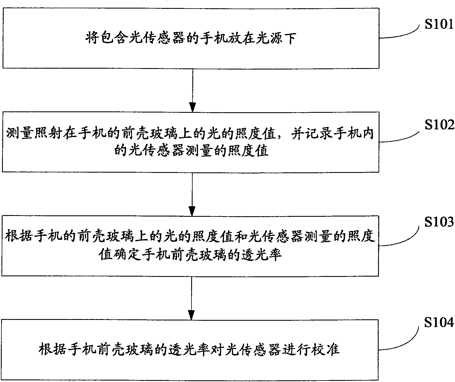
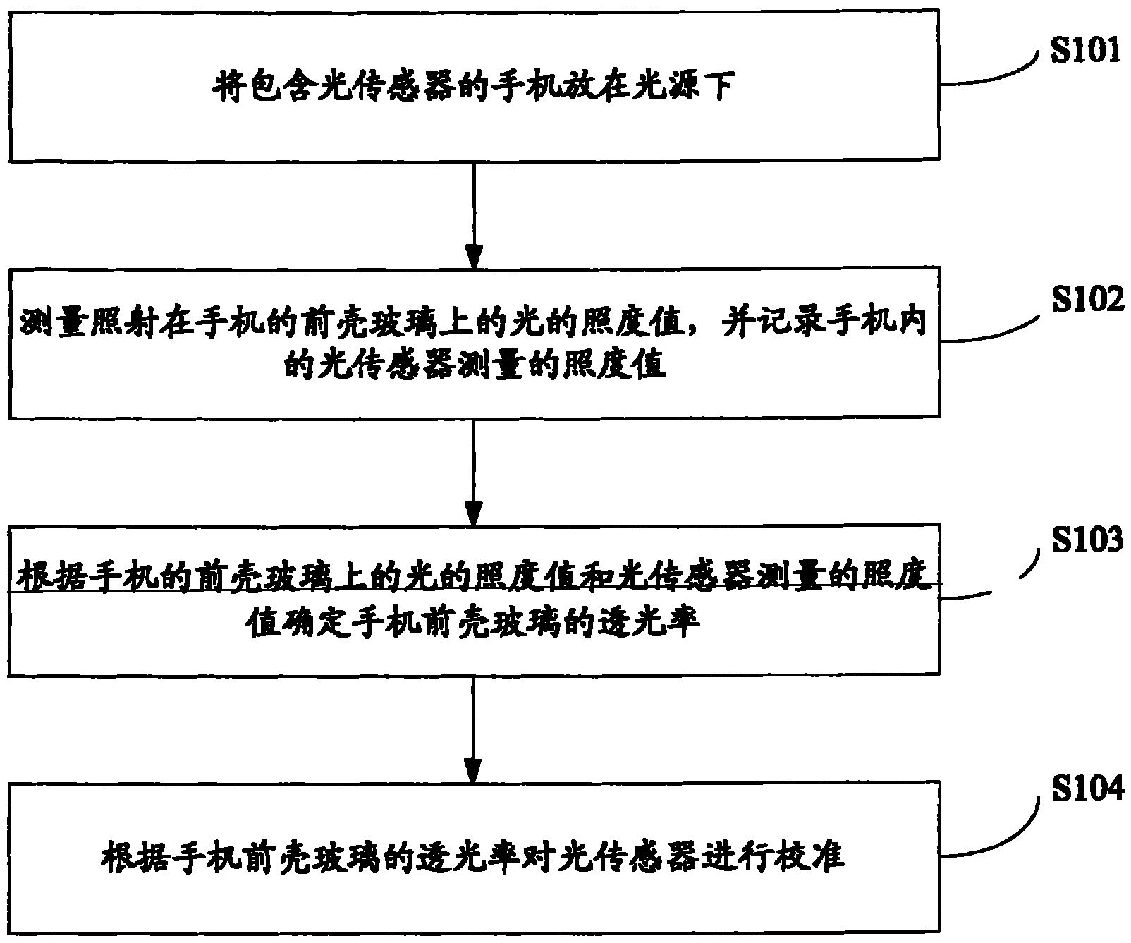
[0013] Embodiments of the present invention are described in detail below, examples of which are shown in the drawings, wherein the same or similar reference numerals designate the same or similar elements or elements having the same or similar functions throughout. The embodiments described below by referring to the figures are exemplary only for explaining the present invention and should not be construed as limiting the present invention.

[0014] In the present invention, it is found that there are mainly six factors affecting the calibration of the light sensor: (1) the sensitivity of the chip itself to light induction; (2) the size of the resistance value; (3) the influence of the power supply; (4) the photosensitive surface of the sensor The distance from the product shell; (5) the size of the lighting aperture; (6) the light transmittance of the glass. Among them, the first three factors can be regarded as internal factors, and the data measured in the actual productio...


PUM


Abstract

The invention provides a method and a system for calibrating an optical sensor of a mobile terminal, wherein the method comprises the following steps: placing the mobile terminal containing the optical sensor under a light source; measuring the illuminating value of light irradiated on the front shell glass of the mobile terminal, and recording an illuminating value measured by the optical sensor in the mobile terminal; determining the light transmission ratio of the front shell glass of the mobile terminal according to the illuminating value of the front shell glass of the mobile terminal and the illuminating value measured by the optical sensor; and calibrating the optical sensor according to the light transmission ratio of the front shell glass of the mobile terminal. According to the invention, the optical sensor is calibrated through referring to the influence of the light transmission ratio of the front shell glass, thus not only can the calibration precision be improved, but also the calibration method is simple and practicable.

Description

technical field [0001] The invention relates to the technical field of electronic equipment manufacturing, in particular to a method and system for calibrating a light sensor of a mobile terminal. Background technique [0002] With the development of communication technology, mobile terminals such as mobile phones are used more and more widely. Due to the mobility of the mobile phone, it is used in environments with different brightness. However, the brightness of the traditional mobile phone screen is fixed, so there is a problem: under the brightness of the indoor light, the brightness of the mobile phone screen is appropriate, but Under the outdoor sunlight, the mobile phone screen will be too dark to see clearly, or in a dim environment, the mobile phone screen will appear too bright and too dazzling, causing damage to the user's eyesight. [0003] Aiming at the above problems, the existing solution is: add a light sensor to the mobile phone to detect the intensity of t...

Claims


Application Information

Patent Timeline
Patent Type & Authority Applications(China)
IPC IPC(8): G01J1/00G01J1/42H04M1/02
Inventor 刘艳霞王文静
Owner BYD CO LTD
Why Eureka
Try Eureka