Pressure switch

A pressure switch and pressure chamber technology, applied in the direction of electric switches, electrical components, circuits, etc., can solve the problems affecting the sensitivity of the switch and the precision of the return diaphragm, so as to improve the precision and sensitivity, high precision of the switch, and structure Design novel effects

Inactive Publication Date: 2012-05-23
郭卫昌
View PDF0 Cites 0 Cited by
  • Summary
  • Abstract
  • Description
  • Claims
  • Application Information

AI Technical Summary

Problems solved by technology

The existing baffle is a layer of metal sheet, which will expand and deform when heated, which will directly affect the accuracy of the return diaphragm, and then affect the sensitivity of the entire switch

Method used


Image

  • Pressure switch
  • Pressure switch
  • Pressure switch

Examples


Embodiment 1

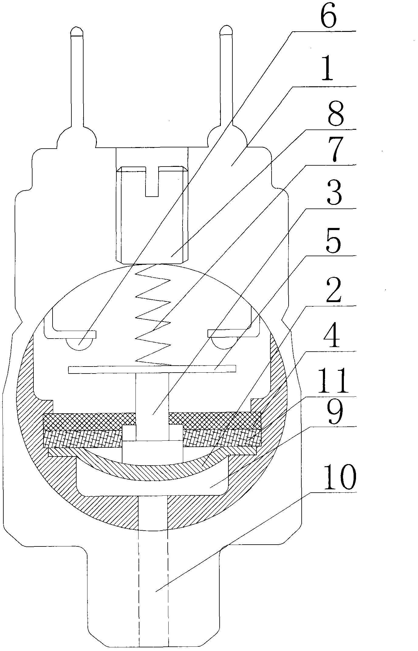
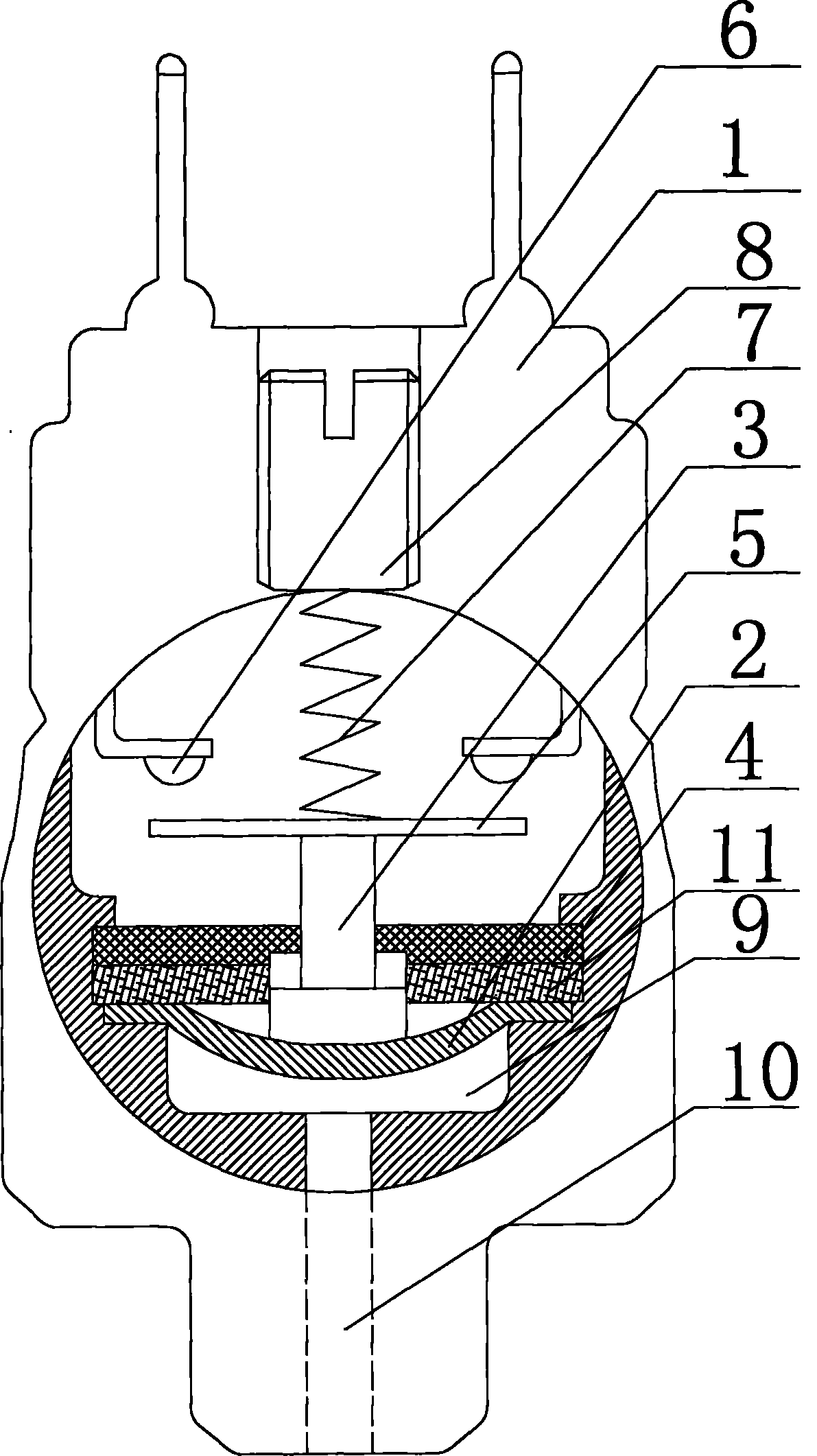
[0013] Such as figure 1 As shown, a pressure switch includes a housing 1, a return diaphragm 2, a ceramic push rod 3, a baffle plate 4, a connecting piece 5 and a connecting contact 6, and the returning diaphragm 2 is placed in the housing 1 , the top of the ceramic mandrel 3 passes through the baffle plate 4 and is connected to the connecting piece 5, the bottom of the ceramic mandrel 3 is in contact with the return diaphragm 2, and the top of the connecting piece 5 is provided with a return spring 7, which passes through the The adjusting screw 8 is fixed in the housing 1, the connecting contact 6 is placed above the connecting piece 5 and there is a gap between the connecting piece 5, and a closed pressure chamber is formed between the return diaphragm 2 and the housing 1 9. A pressure channel 10 communicating with the pressure chamber 9 is provided at the bottom of the housing 1. In order to improve the accuracy and sensitivity of the return diaphragm 2, the baffle 4 is fo...

Embodiment 2

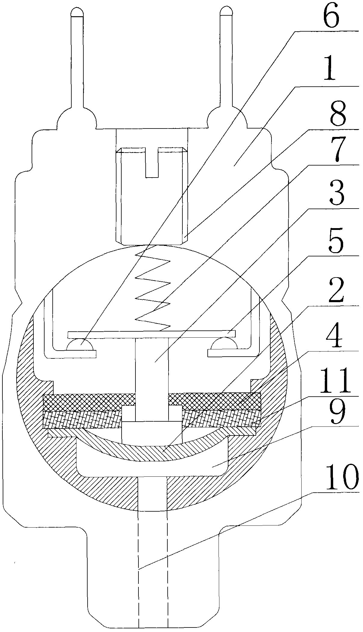
[0016] Such as figure 2 As shown, a pressure switch includes a housing 1, a return diaphragm 2, a ceramic push rod 3, a baffle plate 4, a connecting piece 5 and a connecting contact 6, and the returning diaphragm 2 is placed in the housing 1 , the top of the ceramic mandrel 3 passes through the baffle plate 4 and is connected to the connecting piece 5, the bottom of the ceramic mandrel 3 is in contact with the return diaphragm 2, and the top of the connecting piece 5 is provided with a return spring 7, which passes through the The adjusting screw 8 is fixed in the housing 1, the connecting contact 6 is placed under the connecting piece 5 and is in contact with the connecting piece 5, and a closed pressure chamber 9 is formed between the return diaphragm 2 and the housing 1, The bottom of the casing 1 is provided with a pressure channel 10 communicating with the pressure chamber 9 . In order to improve the precision and sensitivity of the return diaphragm 2 , the baffle 4 is f...


PUM


Abstract

The invention relates to a pressure switch, which comprises a casing, a returning diaphragm, a ceramic top rod, a baffle plate, a connection sheet and a connection contact, wherein the returning diaphragm is arranged in the casing, the top of the ceramic top rod passes through the baffle plate to be connected with the connection sheet, the bottom of the ceramic top rod is in contact with the returning diaphragm, the top of the connection sheet is provided with a reset spring, the reset spring is fixedly arranged in the casing through a regulation screw, the connection contact is arranged above the connection sheet, in addition, gaps are left between the connection contact and the contact sheet, a sealed pressure chamber is formed between the returning diaphragm and the casing, and the bottom of the casing is provided with a pressure passage communicated with the pressure chamber. The pressure switch is characterized in that the baffle plate is formed by overlapping two layers of metal sheets made of different materials. The pressure switch has the advantages that the structure design is novel, the switch precision is high, and the sensitivity is high.

Description

technical field [0001] The present invention relates to a switch, in particular to a pressure switch. Background technique [0002] Pressure switches are generally divided into normally closed switches and normally open switches. Regardless of whether it is a normally closed switch or a normally open switch, a baffle is arranged in the housing. The existing baffle is a layer of metal sheet, and the metal sheet will expand and deform when heated, which will directly affect the precision of the return diaphragm, and then affect the sensitivity of the entire switch. Therefore, a new technical solution is needed to solve the above technical problems. Contents of the invention [0003] The purpose of the present invention is to provide a pressure switch with small temperature difference and strong sensitivity. [0004] The technical scheme adopted in the present invention is: [0005] A pressure switch, comprising a housing, a return diaphragm, a ceramic plunger, a baffle p...

Claims


Application Information

Patent Timeline
IPC IPC(8): H01H35/34
Inventor 郭卫昌
Owner 郭卫昌
Why Eureka
Try Eureka