Planar lighting device and display device having same

A lighting device, planar technology, applied to lighting devices, lighting and heating equipment, light guides of lighting systems, etc., to achieve excellent brightness uniformity and light utilization efficiency

Inactive Publication Date: 2012-05-23
SHARP KK
View PDF8 Cites 8 Cited by
  • Summary
  • Abstract
  • Description
  • Claims
  • Application Information

AI Technical Summary

Problems solved by technology

However, it is difficult for an edge-light lighting device to uniformly inject light into a wide light guide plate using a point light source (LED).

Method used


Image

  • Planar lighting device and display device having same
  • Planar lighting device and display device having same
  • Planar lighting device and display device having same

Examples


Embodiment approach 1

[0080] according to Figure 1 to Figure 11 , Figure 17 ~ Figure 19 One embodiment of the present invention will be described below. In addition, the present invention is not limited thereto, and the dimensions, materials, shapes, relative arrangements, etc. of the components described in the present embodiment are not intended to limit the scope of the present invention thereto unless otherwise specified. , but is only an illustrative example.

[0081]

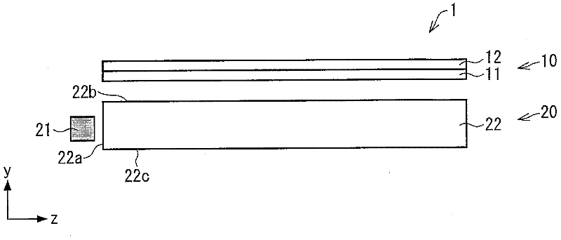
[0082] Such as figure 1 As shown, the liquid crystal display device (display device) 1 of the present invention includes: a liquid crystal display panel (display panel) 10; lighting device) 20; and a frame (not shown) for accommodating the liquid crystal display panel 10 and the backlight device 20. In addition, the liquid crystal display device 1 is an example of the "display device" of the present invention, the liquid crystal display panel 10 is an example of the "display panel" of the present invention, and the bac...

Embodiment approach 2

[0145] according to Figure 12 to Figure 14 , Figure 20 ~ Figure 22 Other embodiments of the optical component related to the present invention will be described below. In addition, for convenience of description, components having the same functions as those in the drawings described in Embodiment 1 are denoted by the same reference numerals, and description thereof will be omitted.

[0146]

[0147] Figure 12 (a) is a perspective view showing a schematic configuration of a backlight device according to this embodiment, Figure 12 (b) and (c) are side views showing a schematic configuration of the backlight unit according to the present embodiment, Figure 12 (d) is a plan view showing a schematic configuration of the backlight unit of the present embodiment.

[0148] Such as Figure 12 As shown in (b), in the backlight device of this embodiment, the low-refractive-index layer 24 is provided between the light guide body 22 and the reflection plate 25 . In addition, ...

Embodiment approach 3

[0172] according to Figure 15 , Figure 16 Other embodiments of the optical component related to the present invention will be described below. In addition, for convenience of description, components having the same functions as those in the drawings described in Embodiment 1 are denoted by the same reference numerals, and description thereof will be omitted.

[0173]

[0174] Figure 15 (a) is a perspective view showing a schematic configuration of a backlight device according to this embodiment, Figure 15 (b) and (c) are side views showing a schematic configuration of the backlight unit according to the present embodiment, Figure 15 (d) is a plan view showing a schematic configuration of the backlight unit of the present embodiment.

[0175] Such as Figure 15 As shown in (b), in the backlight device of this embodiment, the light guide member 23 includes: a substantially cuboid or substantially square light guide 22 made of a transparent material with a refractive ...


PUM


Abstract

Provided are a planar lighting device having excellent luminance uniformity and excellent light utilization efficiency, and a display device provided with the planar lighting device. The planar lighting device includes a light guide element (22) having: a first optical member formed in a light entry face (22a) for allowing light emitted from a light source (21) to enter into the light guide element (22) while diffusing the light; a second optical member formed in a light exit face (22b) or a back face (22c) for changing the angle of the light inside the light guide element; a third optical member formed in the light exit face (22b) or the back face (22c) for diffusing the light inside the light guide element (22); and a fourth optical member formed in the light exit face (22b) or the back face (22c) at a position on the side of the light entry face (22a) for condensing, inside the light guide element (22), the light diffused by the first optical member. The fourth optical member is formed to have a recessed shape toward the light exit face (22b) or the back face (22c).

Description

technical field [0001] The present invention relates to a planar lighting device and a display device including the same. More specifically, it relates to a planar lighting device excellent in luminance uniformity and light use efficiency, and a display device including the same. Background technique [0002] In recent years, liquid crystal display devices, which have rapidly spread instead of cathode ray tubes (CRTs), are widely used in liquid crystal televisions, monitors, and mobile phones that are energy-saving, thin, and lightweight. As a method for further utilizing these advantages, improvement of an illumination device (so-called backlight) arranged behind a liquid crystal display device can be mentioned. [0003] Illumination devices are roughly classified into an edge-light type (also referred to as an edge type) and a direct-light type. The direct lighting device is a lighting device in which a plurality of light sources are arranged behind the liquid crystal di...

Claims


Application Information

Patent Timeline
Patent Type & Authority Applications(China)
IPC IPC(8): F21S2/00G02F1/13357F21Y101/02
CPCG02B6/0016G02B6/0038G02B6/005G02B6/0061
Inventor 国政文枝
Owner SHARP KK
Why Eureka
Try Eureka