Burner, in particular for gas turbines

A burner and combustion air technology, applied in the direction of burner, combustion chamber, combustion method, etc., can solve the problem of changing the design of the burner

Active Publication Date: 2014-08-20
SIEMENS ENERGY GLOBAL GMBH CO & KG
View PDF9 Cites 0 Cited by
  • Summary
  • Abstract
  • Description
  • Claims
  • Application Information

AI Technical Summary

Problems solved by technology

The difficulty now lies in supplying fuel to this additional gas channel without aerodynamically altering the burner design to date

Method used


Image

  • Burner, in particular for gas turbines
  • Burner, in particular for gas turbines
  • Burner, in particular for gas turbines

Examples


Embodiment Construction

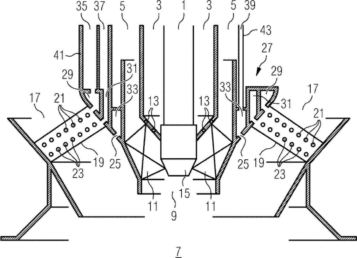
[0028] The burner according to the invention is shown in a clearly schematic schematic diagram below with reference to figure 1 Describe the scheme that is the basis for the burner.

[0029] A burner according to the invention can optionally be arranged in combination with several burners of the same type in the combustion chamber of a gas turbine plant, the burner comprising an inner pilot burner system and a main combustion chamber concentrically surrounding the pilot burner system device system. Both the pilot burner system and the main burner system can optionally be operated with gaseous and / or liquid fuels such as natural gas or fuel oil.

[0030] The pilot burner system comprises an inner oil delivery channel 1 which is concentrically surrounded by an inner annular gas delivery channel 3 . This gas delivery channel is in turn surrounded concentrically by the inner air delivery channel or inert gas delivery channel 5 . Furthermore, a suitable ignition system (not show...


PUM


Abstract

The burner, particularly a gas turbine burner, comprises a central fuel supply arrangement (27) and an annular air-duct (17) for supplying combustion air and twisting the blades (19) that are arranged in the annular air-duct. The gas nozzles (21) are provided in the fuel supply arrangement by a gas distributor channel (29). Other gas nozzles (23) are provided in the fuel supply arrangement by another gas distributor channel (31). A gas supply pipe (41) has a gas supply channel (35).

Description

technical field [0001] The invention relates to a combustor, and in particular a gas turbine combustor, with a central fuel supply. Furthermore, the invention relates to a gas turbine. Background technique [0002] In view of the worldwide efforts to reduce pollutant emissions in combustion plants, especially gas turbines, burners with particularly low nitrogen oxide (NOx) emissions have been developed in recent years. In this case, it is expediently provided that such burners can each be operated not only with one fuel, but possibly also with different fuels, for example oil and natural gas or a combination of both, in order to increase the security of supply and the flexibility of operation. sex. Such a burner is described, for example, in EP0276696B1. [0003] The burners described in EP0276696B1 are hybrid burners operated with a premixed gas and / or oil, such as are used in particular for gas turbine installations. The burner comprises a central combustion delivery, ...

Claims


Application Information

Patent Timeline
Patent Type & Authority Patents(China)
IPC IPC(8): F23R3/28F23R3/14
CPCF23R3/14F23R3/286F23D2211/00F23C2900/07001F23R2900/00001F23D2900/14021F23R3/283
Inventor A.波特克M.卡诺沃尔夫A.克鲁格T.克雷格U.沃兹
Owner SIEMENS ENERGY GLOBAL GMBH CO & KG
Why Eureka
Try Eureka