Exhaust manifold

A technology of exhaust elbow and exhaust port, which is applied in the direction of exhaust treatment, exhaust device, silencer device, etc., to achieve the effect of reducing the number of parts, reliable and simple method, and simple structure

Active Publication Date: 2016-05-18
BENTELER AUTOMOBILTECHNIK GMBH
View PDF11 Cites 0 Cited by
  • Summary
  • Abstract
  • Description
  • Claims
  • Application Information

AI Technical Summary

Problems solved by technology

What is troublesome in this case is the additional seal between the external system or the exhaust gas collection housing and the fastening via the fixing

Method used


Image

  • Exhaust manifold
  • Exhaust manifold
  • Exhaust manifold

Examples


Embodiment Construction

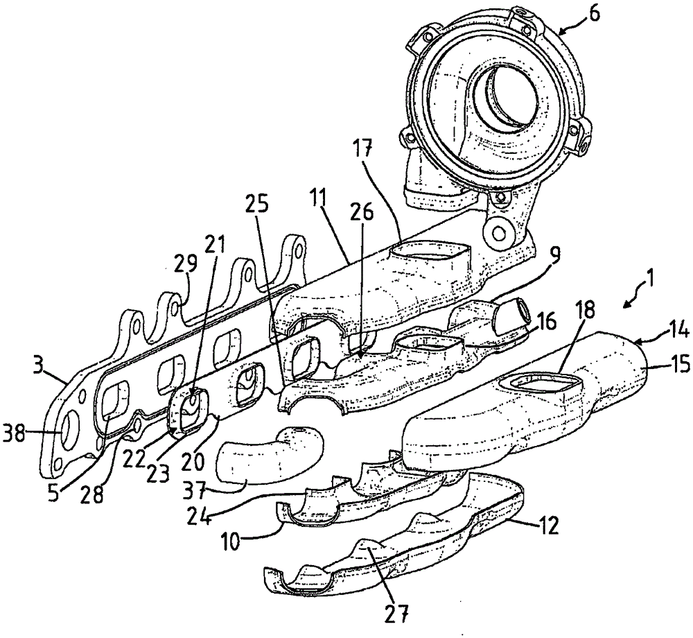
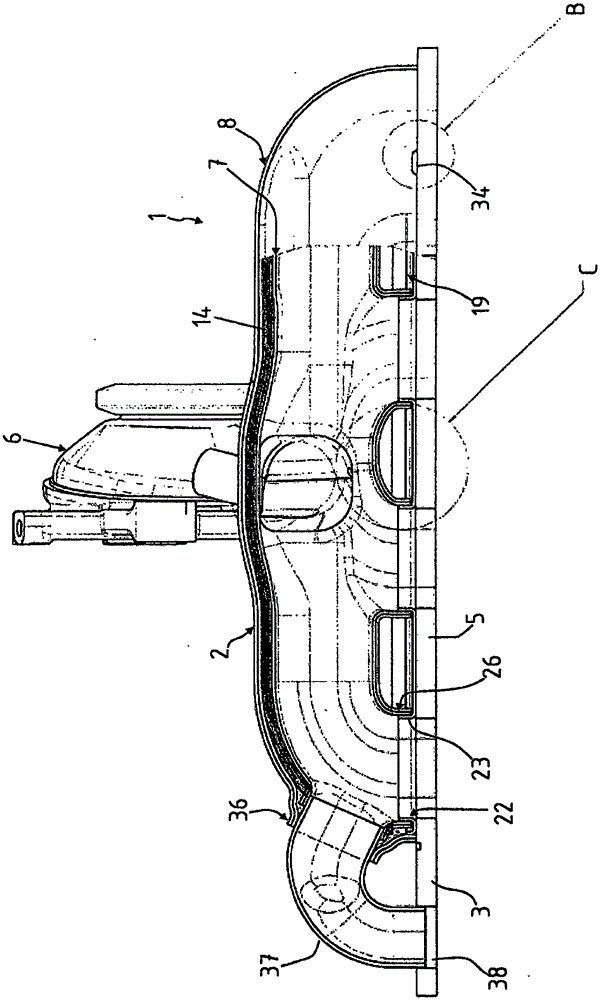
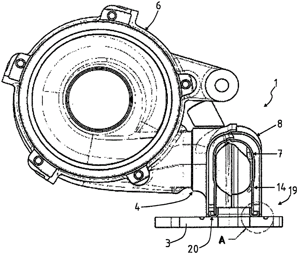
[0034] With the help of Figure 1-6 The illustration shows an exhaust manifold 1 according to the invention of an exhaust system of an internal combustion engine. Figure 7 A variant of the exhaust manifold 1 is shown. The exhaust manifold 1 can be fastened to a cylinder head (not shown here) of a motor vehicle internal combustion engine.

[0035] The exhaust elbow 1 comprises a housing 2 with an inlet flange 3 and an exhaust hole 4 . The exhaust manifold 1 is attached via the intake flange 3 to the cylinder head of the internal combustion engine. The intake flange 3 has a plurality of intake openings 5 ​​, via which the exhaust gases from the individual cylinders are diverted into the exhaust manifold 1 . The exhaust gas is conveyed via the exhaust opening 4 to a downstream component of the exhaust system, for example an exhaust gas turbocharger 6 as shown here.

[0036]The housing 2 comprises an inner shell 7 and an outer shell 8 . The inner shell 7 consists of two shel...


PUM


Abstract

An exhaust manifold 1 for an exhaust system of an internal combustion engine is disclosed having a housing 2, an inlet flange 3 which can be fixed to the cylinder head of the internal combustion engine and has a plurality of inlet openings 5, and an exhaust outlet 4. The housing 2 comprises an inner shell 7 and an outer shell 8, an insulating material 14 being incorporated between the outer shell 8 and the inner shell 7. A guide plate 20 is provided on the inlet flange side of the inner shell and the outer shell 8. The guide plate has inflow openings which correspond with the inlet openings 5 of the inlet flange 3 and is joined to the inlet flange 3. The outer shell engages with its inlet flange-side edge around the guide plate 20 and is joined to the inlet flange and the guide plate 20.

Description

technical field [0001] The invention relates to an exhaust manifold for an exhaust system of an internal combustion engine according to the features stated in the preamble of claim 1 . Background technique [0002] The exhaust elbow is a part of the exhaust system of an internal combustion engine, especially a vehicle internal combustion engine. The exhaust manifold, which is attached directly to the cylinder head of the internal combustion engine, collects the exhaust gases from the individual cylinders and directs them to the exhaust ports. The exhaust manifold is therefore often also referred to as an exhaust gas collector. [0003] The exhaust elbow that isolates the air gap belongs to the prior art through US5729975A. The exhaust manifold has an inner pipe system and a jacket surrounding the inner pipe system with a distance, as well as an inlet flange and an outlet flange. The exhaust manifold known from DE 10102637 A1 also has an inner tube system formed there as a...

Claims


Application Information

Patent Timeline
IPC IPC(8): F01N13/10
CPCF01N13/10F01N13/102F01N13/1811F01N13/1872F01N13/1888F01N2260/08F01N2260/10F01N2450/22F01N1/24F01N13/14F01N13/18
Inventor U·菲舍尔E·格鲁斯曼T·戈克尔
Owner BENTELER AUTOMOBILTECHNIK GMBH
Why Eureka
Try Eureka