Warp knitting machine

A warp knitting machine and frame technology, applied in the field of warp knitting machines, can solve problems such as high cost

Inactive Publication Date: 2016-01-20
KARL MAYER TEXTILMASCHFAB GMBH
View PDF7 Cites 0 Cited by
  • Summary
  • Abstract
  • Description
  • Claims
  • Application Information

AI Technical Summary

Problems solved by technology

However, relatively high costs arise in the production and operation of the warp knitting machine, since the heating device has to be installed and operated, wherein the operation of the heating device results in a non-negligible energy consumption

Method used


Image

  • Warp knitting machine
  • Warp knitting machine
  • Warp knitting machine

Examples


Embodiment Construction

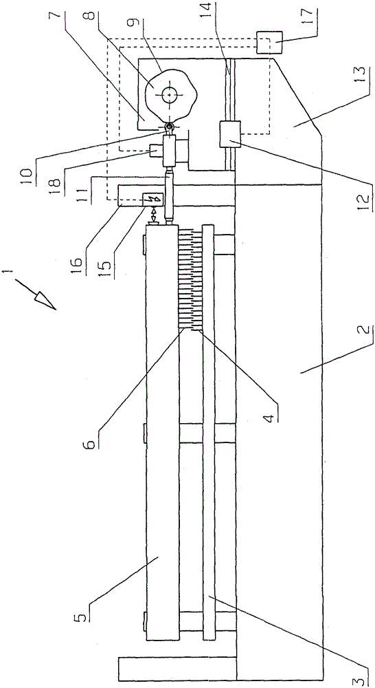
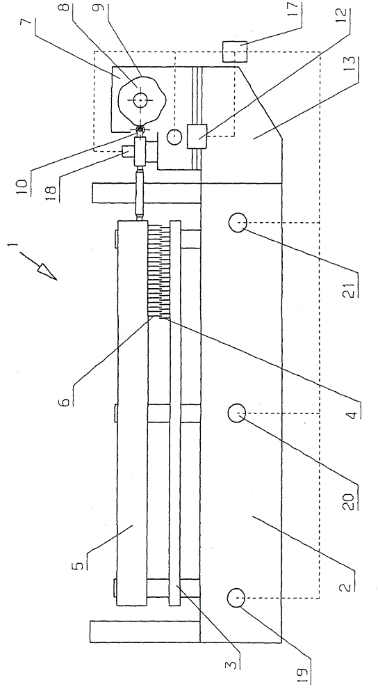
[0031] figure 1 In very schematic form, a warp knitting machine 1 is shown with a frame 2 carrying a needle bed 3 on which needles 4 are arranged side by side. Arranged in the frame 2 is a spindle, not shown in detail, which moves a needle bed 3 (shown in simplified form) upwards and downwards.

[0032] The frame 2 also carries the bar 5 on which the guide needle 6 is arranged. Drive the bar 5 via the main shaft in a manner known per se, so that the guide needle 6 is perpendicular to the drawing plane (relating to figure 1 icon) swing. Here, the bar 6 passes through the gaps between the knitting needles 4 .

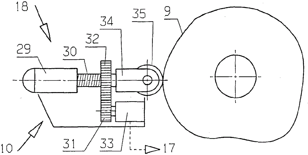
[0033] Arranged at the end of the machine frame 2 is a jacquard device 7 , which in the present case has a cam disc 8 . The cam disc 8 has a control surface 9 at its periphery. A displacement slide 10 acts as a transmission element on the control surface 9 , which acts on the bar 5 via a push rod 11 and drives the bar 5 in the mentioned displacement direction. The d...


PUM


Abstract

The warp knitting machine (1) has machine frame (2), positioning rod (5) and pattern device (7) with circulating control surface (9). The pattern device drives the positioning rod in a displacement direction. A correction drive (12,18) moves the pattern device in displacement direction using reduction gears and jackscrew actuator.

Description

technical field [0001] The invention relates to a warp knitting machine with a frame, at least one bar and a jacquard device with a surrounding control surface, which drives the bar in a displacement direction. Background technique [0002] Such a warp knitting machine is known, for example, from DE19504467C2. [0003] In warp knitting machines, the knitting needles (Wirknadel) and thread guide needles (Legenadel) work together to produce knitted fabrics. The knitting needles are generally arranged on the knitting needle bed and the yarn guide needles are arranged on the yarn guide needle bed. The thread guide needle bed is displaceable by the jacquard device in the direction of displacement, that is to say in the direction of its longitudinal extension. Furthermore, the comb bar can be swung transversely to the displacement direction. During this pivoting movement, the guide needles are guided through the gaps between the knitting needles. [0004] The spacing between a...

Claims


Application Information

Patent Timeline
Patent Type & Authority Patents(China)
IPC IPC(8): D04B23/00D04B27/00
CPCD04B27/26
Inventor H.万泽
Owner KARL MAYER TEXTILMASCHFAB GMBH
Why Eureka
Try Eureka