Shadow maske frame assembly for color cathode ray tube

A cathode ray tube and shadow mask technology, applied in the field of color cathode ray tubes, can solve the problems of limited compensation for the expansion of the shadow mask plate 21a, high cost, and complicated manufacturing of shadow mask frame components.

Inactive Publication Date: 2003-12-17
SAMSUNG ELECTRONICS DEVICES CO LTD
View PDF0 Cites 0 Cited by
  • Summary
  • Abstract
  • Description
  • Claims
  • Application Information

AI Technical Summary

Problems solved by technology

[0008] However, since the shadow mask 21 is supported to the frame 22 with its side edge portion 21c fixed to the support wall 22a of the frame 22, there is a limit to the compensation for the ex

Method used


Image

  • Shadow maske frame assembly for color cathode ray tube
  • Shadow maske frame assembly for color cathode ray tube
  • Shadow maske frame assembly for color cathode ray tube

Examples


Embodiment Construction

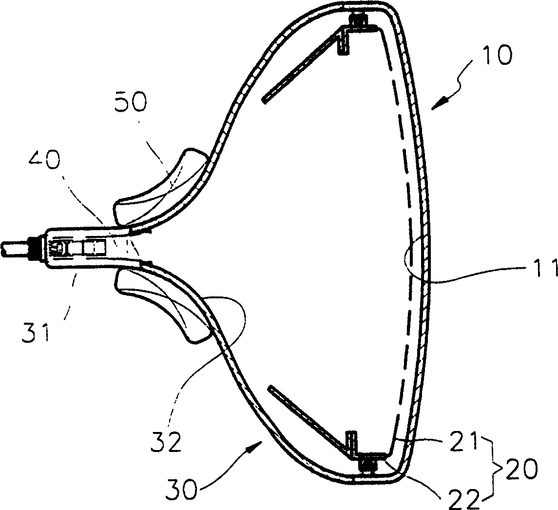
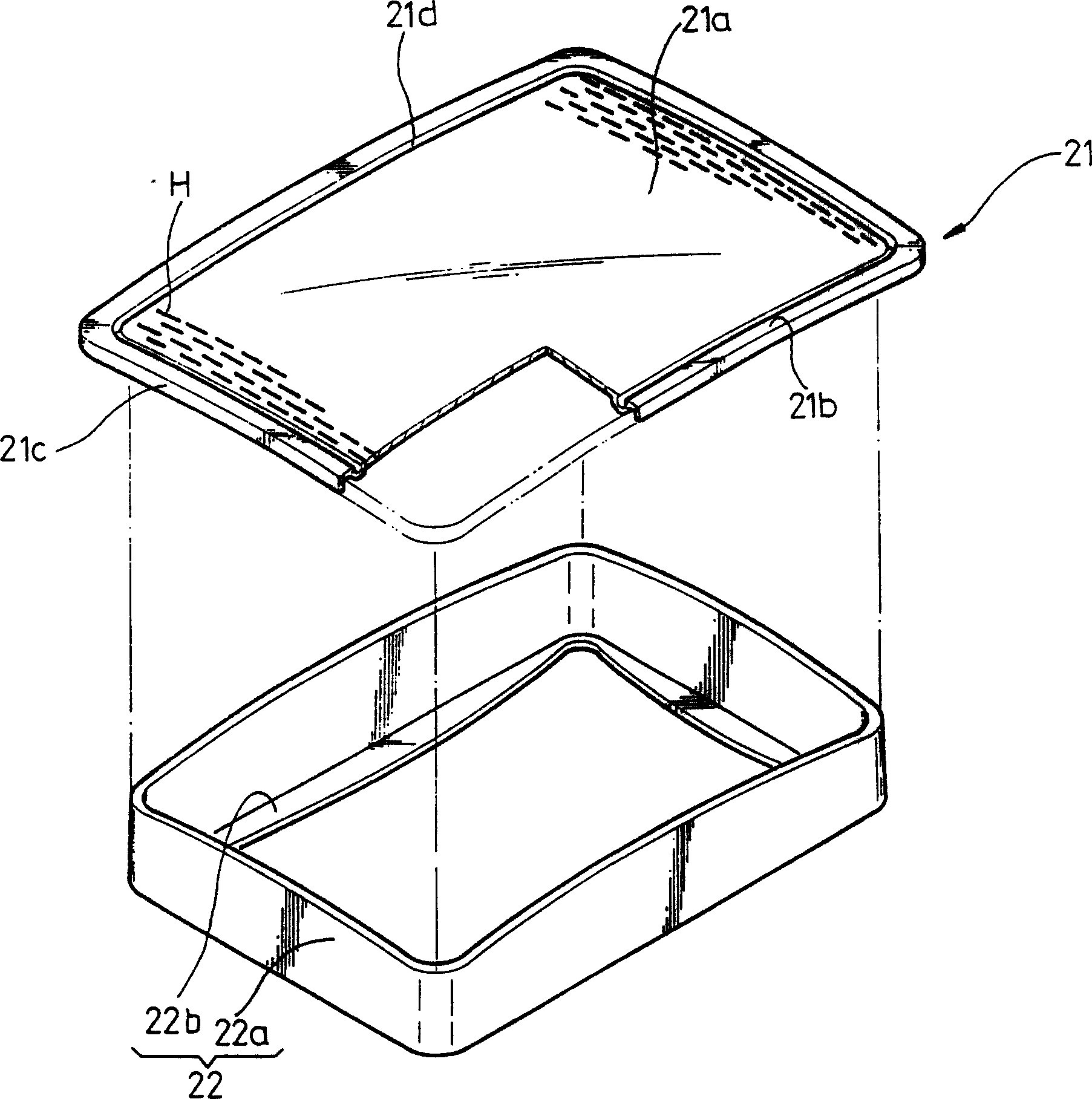
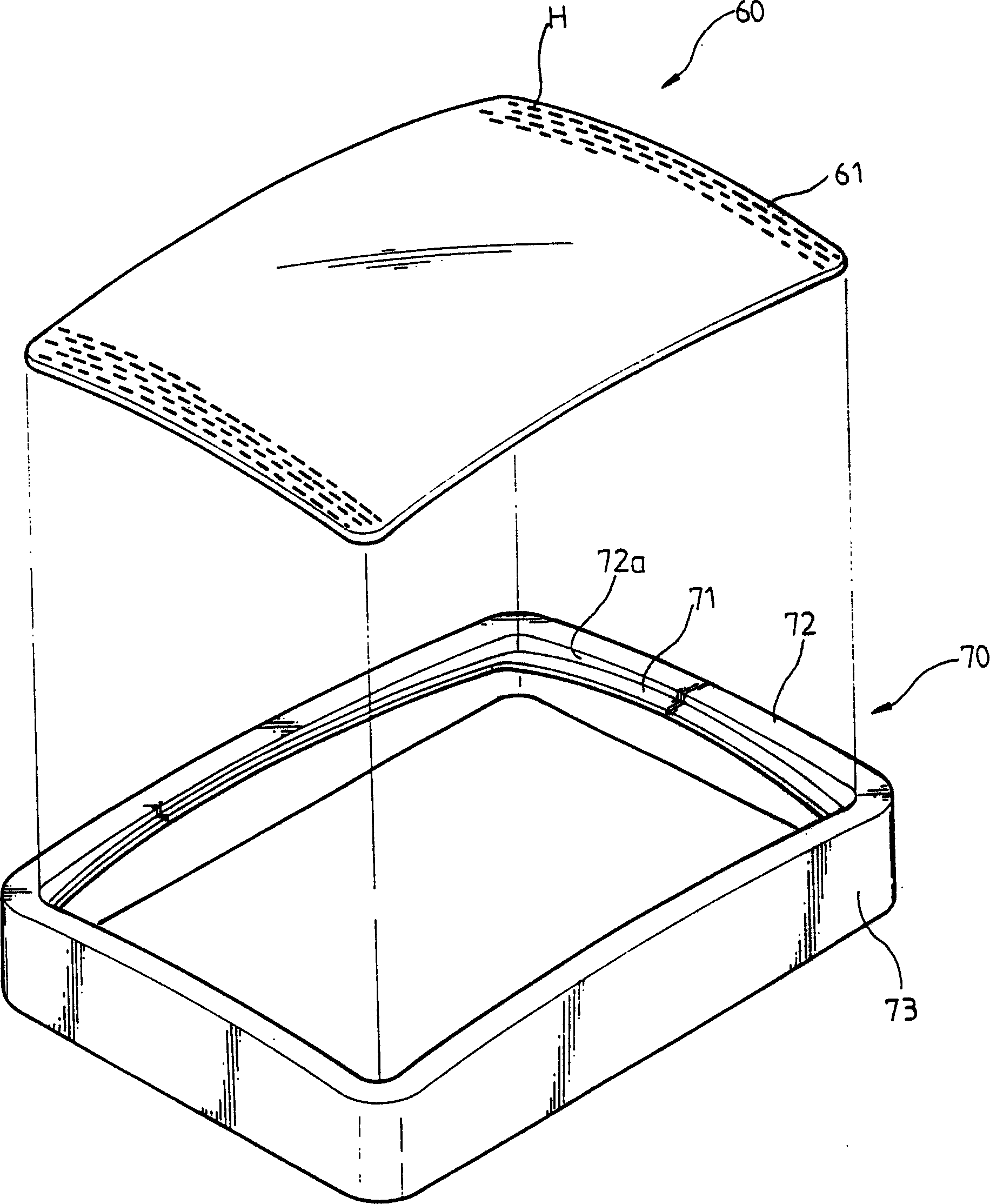
[0017] Refer to image 3 with Figure 4 , The shadow mask frame assembly includes a shadow mask 60 and a frame 70 that are coupled to each other. The shadow mask 60 on which a plurality of electron beam through holes H are formed is a plate having a predetermined curvature. With conventional shadow mask 21 ( figure 2 ) Is different. In the shadow mask 60 according to the present invention, the side edge part ( figure 2 21c).

[0018] The shadow mask 60 may have different curvatures in diagonal and horizontal / vertical directions. Compared to a flat panel, the radius of curvature of the shadow mask 60 is preferably made larger.

[0019] The frame 70 includes a flange 72 extending inward from the side wall 73 and having a predetermined curvature, and a support portion 71 extending from the flange 72 and having a curvature corresponding to the shadow mask 60.

[0020] The radius of curvature of the support portion 71 is smaller than the radius of curvature of the flange 72. The suppo...


PUM


Abstract

A shadow mask frame assembly for a color cathode ray tube including a plate shaped shadow mask including electron beam passing holes and having a curvature, and a frame having a side wall, a flange inwardly extending from the side wall, and a supporting portion extending from the flange as a step, wherein some peripheral edges of the shadow mask are attached to the supporting portion and some peripheral edges of the shadow mask are not attached to the supporting portion and slip on an upper surface of the supporting portion during thermal expansion of the shadow mask.

Description

Technical field [0001] The present invention relates to a color cathode ray tube, and more particularly to a shadow mask frame assembly that allows an electron beam emitted from an electron gun to accurately scan on a fluorescent film. Background technique [0002] Refer to figure 1 , figure 1 Representing a conventional color cathode ray tube (CRT), a fluorescent film 11 is formed on the inner side of the panel 10, and the shadow mask frame assembly 20 is separated from the fluorescent film 11 by a predetermined distance. The shadow mask frame assembly 20 is composed of a shadow mask 21 facing the fluorescent film 11 and a frame 22 for supporting the shadow mask 21. The panel 10 is connected to a funnel portion 30, which includes a neck portion 31 having an electron gun 40 installed therein, and a cone portion 32 having a deflection yoke 50. [0003] Such as figure 2 As shown, the shadow mask 21 includes a shadow mask 21a having a plurality of electron beam through holes H, a...

Claims


Application Information

Patent Timeline
IPC IPC(8): H01J29/07
CPCH01J29/073H01J29/07
Inventor 李善行
Owner SAMSUNG ELECTRONICS DEVICES CO LTD
Why Eureka
Try Eureka