Pump

A pump shaft and two-stage pump technology, applied in the field of pumps, can solve the problems of multiple pollution emissions, multiple fuel consumption, etc.

Inactive Publication Date: 2012-05-30
MAHLE INT GMBH
View PDF6 Cites 0 Cited by
  • Summary
  • Abstract
  • Description
  • Claims
  • Application Information

AI Technical Summary

Problems solved by technology

Cooling is therefore not only unnecessary, but even undesirable, especially during the cold start phase of an internal co...

Method used


Image

  • Pump
  • Pump
  • Pump

Examples


Embodiment Construction

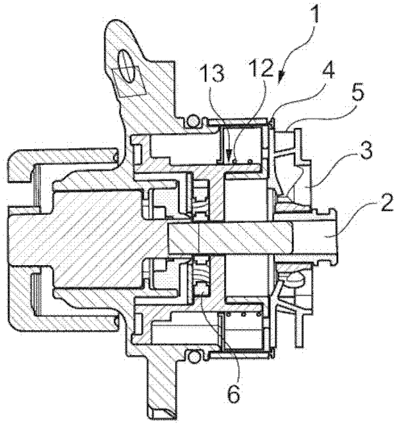
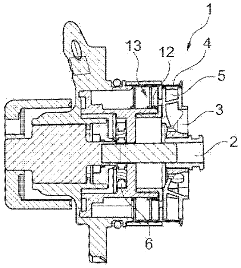
[0021] Such as figure 1 As shown, a pump 1 (which can be configured, for example, as a cooling pump in a motor vehicle) has a pump shaft 2 on which an impeller 3 (also referred to as pump wheel) is arranged in a rotatably fixed manner. The impeller 3 conveys liquid, for example cooling liquid, by means of a rotational movement about the axis of the pump shaft 2 . Furthermore, according to the invention, the pump 1 has an adjustable sliding valve 4 which can slide like a sleeve on the impeller 3, thereby closing the outlet 5 more or less and controlling the delivery speed of the pump 1 . The sliding valve 4 is movable in the axial direction of the pump 1 . Also mounted on the pump shaft 2 is a piston pump 6 (shown in Figures 2 to 4) for generating hydraulic pressure that can control the slide valve 4, which means regulating it. In addition, a valve device 7 is provided to separate or connect the suction side and the pressure side of the piston pump 6 , thereby controlling the...


PUM


Abstract

The pump (1) has an impeller (3) that is located on a pump shaft (2). An adjustable slider (4) is displaced over the impeller to control delivery rate of fluid pressure from a main portion. A displacement pump (6) is arranged on pump shaft to set steering fluid pressure in main portion. A valve (7) is provided to separate the suction side and pressure side of the displacement pump.

Description

technical field [0001] The invention relates to a pump, especially a cooling pump in a motor vehicle, the pump includes an impeller arranged on the pump shaft. Background technique [0002] Cooling pumps in motor vehicles are usually used to control the flow of coolant for cooling the internal combustion engine, wherein the delivery rate of such a cooling pump depends on the cooling requirements. Cooling is therefore not only unnecessary, but even undesirable, especially during the cold start phase of an internal combustion engine, since it prolongs the cold start phase, resulting in more fuel consumption and thus more polluting emissions. The management or control of the delivery rate of the cooling pump usually takes place via electromagnetically controllable valves or couplings or different valves. Contents of the invention [0003] The technical problem underlying the present invention is to provide an improvement of a pump, in particular a cooling pump, which is desi...

Claims


Application Information

Patent Timeline
IPC IPC(8): F04D13/02
CPCF04D15/0038F04D5/002F05D2270/64F01P5/10F01P7/14F01P11/00
Inventor 米夏埃尔·鲍曼冈瑟·比兹霍尔格·康拉德奥利弗·格布哈特鲁迪格·克瑙斯克里斯蒂安·里希特
Owner MAHLE INT GMBH
Why Eureka
Try Eureka