Single-phase insulating and rectifying transformer

A rectifier transformer, single-phase technology, applied in the direction of transformer/inductor magnetic core, transformer/inductor parts, transformer/inductor coil/winding/connection, etc., can solve fire safety hazards and easily generate high-order harmonics current, environmental pollution and other problems, to achieve the effect of suppressing the generation of high-order harmonics, improving the quality of power supply, and improving safety

Active Publication Date: 2012-05-30
TEBIAN ELECTRIC APP CO LTD
View PDF2 Cites 6 Cited by
  • Summary
  • Abstract
  • Description
  • Claims
  • Application Information

AI Technical Summary

Problems solved by technology

[0002] At present, traction stations of electrified railways often use 27.5kV single-phase isolation transformers to provide power to SVG inverter dynamic reactive power compensation power supply devices. Moreover, single-phase isolation transformers mostly use oil-immersed transformers. This type of oil-immersed transformer has the following disadvantages: First, the secondary winding (valve side) is prone to high-order harmonic current, and the high-order harmonic content is high, so that the rectifier transformer cannot provide a balanced and stable voltage, which seriously affects the power supply of the SVG inverter dynamic reactive power compensation power supply device quality, while affecting the service life of the transformer; second, oil-immersed transformers are prone to oil leakage, which poses environmental pollution and fire safety hazards; third, the current oil-immersed transformers cannot be used for temperature control systems, cooling systems and lighting The system provides electric energy, and the user also needs to purchase an independent power supply device for supplying power to the temperature control system, cooling system or lighting system, which will not only increase the space for installing the control power supply, but also increase the initial investment cost of the user; fourth, inside the transformer Partial discharge is inevitable, which will cause the transformer oil to decompose and produce gas or other harmful gases, which will cause the transformer to fail and affect the quality of power supply

Method used


Image

  • Single-phase insulating and rectifying transformer
  • Single-phase insulating and rectifying transformer
  • Single-phase insulating and rectifying transformer

Examples


Embodiment Construction

[0023] In order to enable those skilled in the art to better understand the technical solution of the present invention, the single-phase isolation rectifier transformer of the present invention will be described in detail below with reference to the accompanying drawings.

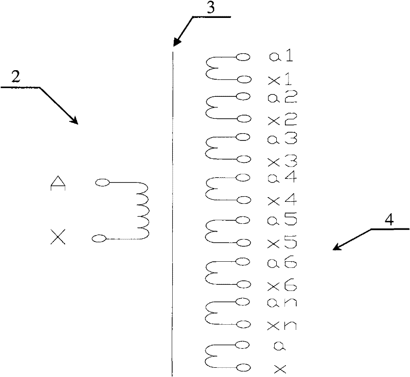
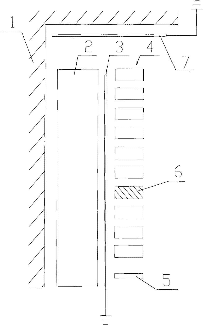
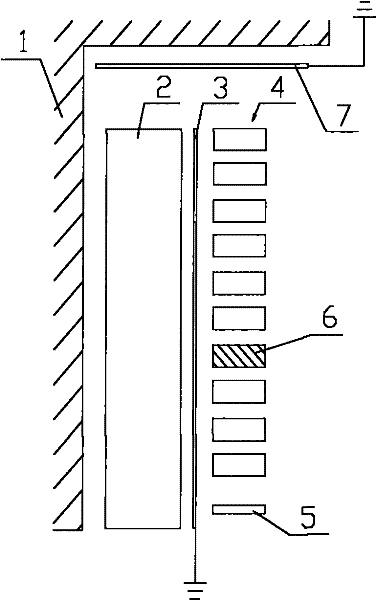
[0024] see figure 1 with figure 2 , is the electrical principle diagram and a partial diagram of the internal structure of the single-phase isolation rectifier transformer of the present invention. In this embodiment, the single-phase isolated rectifier transformer adopts a dry-type rectifier transformer, which includes an iron core 1, a primary winding 2, a first electric shielding component 3, a secondary winding 4, an auxiliary winding 5, a spare unit segment 6 and a second Electric shielding part 7.

[0025] Among them, core 1 is a cold-rolled grain-oriented electrical silicon steel sheet, which is superimposed by a 45° three-stage fully oblique joint method, and is fixed by the relatively advanced ...


PUM


Abstract

The invention provides a single-phase insulating and rectifying transformer, comprising an iron core (1), a primary winding (2) and a secondary winding (4), wherein the iron core (1) comprises an upper iron yoke and a lower iron yoke; and the primary winding is wound on the iron core; and the secondary winding is arranged at the outer side of the primary winding. The single-phase insulating and rectifying transformer further comprises a first electric screening component (3), wherein the first electric screening component is arranged between the primary winding (2) and the secondary winding (4). The single-phase insulating and rectifying transformer can reduce higher harmonic waves generated by the secondary winding so as to improve current waveform of the secondary winding and prolong service life of the transformer. Therefore, the power supply quality of a 27.5 kV power rectifying system in an electrified railway rail traction station is further improved.

Description

technical field [0001] The invention relates to a single-phase isolated rectifier transformer. Background technique [0002] At present, traction stations of electrified railways often use 27.5kV single-phase isolation transformers to provide power to SVG inverter dynamic reactive power compensation power supply devices. Moreover, single-phase isolation transformers mostly use oil-immersed transformers. This type of oil-immersed transformer has the following disadvantages: First, the secondary winding (valve side) is prone to high-order harmonic current, and the high-order harmonic content is high, so that the rectifier transformer cannot provide a balanced and stable voltage, which seriously affects the power supply of the SVG inverter dynamic reactive power compensation power supply device quality, while affecting the service life of the transformer; second, oil-immersed transformers are prone to oil leakage, which poses environmental pollution and fire safety hazards; thi...

Claims


Application Information

Patent Timeline
Patent Type & Authority Applications(China)
IPC IPC(8): H01F27/36H01F27/28H01F27/30H01F27/26H01F27/245
Inventor 魏月刚房玉杰
Owner TEBIAN ELECTRIC APP CO LTD
Why Eureka
Try Eureka