
Method of safe transfer of filter segments in process of producing multi-segment filters

A filter and transmission component technology, applied in the field of safe transmission, can solve the problems of transmission component collision, damaged component production, segment error placement, etc.

Active Publication Date: 2013-10-30
PHILIP MORRIS PROD SA
View PDF10 Cites 1 Cited by
  • Summary
  • Abstract
  • Description
  • Claims
  • Application Information

AI Technical Summary

Problems solved by technology

If the segment is good quality, but the component that placed the segment on the riser places the segment incorrectly before placing each subsequent segment, or subsequent components place the segment out of sync with each other, it may result in a segment with an earlier placed segment on the riser Teleport components collided
This defect can damage components and create the risk of making incomplete multi-segment filter rods
Existing attempts to protect certain parts of an assembly from damage do not protect the entire process from fully functioning

Method used


Image

  • Method of safe transfer of filter segments in process of producing multi-segment filters
  • Method of safe transfer of filter segments in process of producing multi-segment filters
  • Method of safe transfer of filter segments in process of producing multi-segment filters

Examples


Embodiment Construction

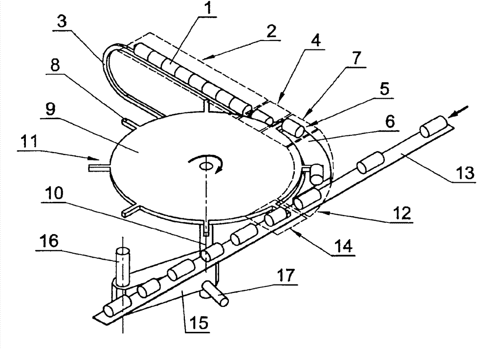
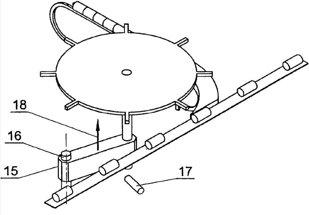
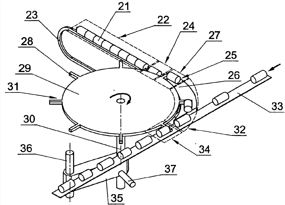
[0005] Example I. figure 1 The situation shown, in which suitable segments 1 are to be made is conveyed in finished strings through zones 2 to 4 comprising a conveyor 3 where the segments are separated by a separating assembly 5 which is a fixed ramp 6, and is conveyed in zone 7 between drives 8 of rotating discs 9 mounted perpendicular to the horizontal axis 10, which constitute a conveying assembly 11. Said separated segment 1 intercepted by the drive 8 in zone 7 is conveyed individually to zone 12 and placed on the horizontal trajectory of the gang belt 13 in zone 14, by which it is conveyed to the next module to produce the desired segment 1 . The shaft 10 of said disc 9 is mounted in a horizontally extending arm 15 slidably mounted on a guide 16 parallel to the shaft 10 , which incorporates a sensor 17 mounted near the shaft 10 . The sensor 17 detects that the position of the disc 9 together with the shaft 10 changes, or the resistance of the movement of the machine inc...


PUM


Abstract

In the manufacture of segment filters, appropriately prepared segments (1) are transferred through a delivery zone (2) to a separation zone (4) equipped with a separating unit (5), and then transferred between the drivers (8) of a rotating disk (9) mounted on axis (10), which constitutes a transferring unit (11), and intercepted by the said unit (11.) in an interception zone (T), they are transferred individually through a transfer zone (12) to a placement zone (14), where they are positioned on the horizontal track of the grouping belt (13), and in the case of incorrect flow of filter segments (1) in any zone (2, 4, 7, 12, 14) and / or between the zones, the process of the transfer of the filter segments in at least one zone is interrupted, which causes the interruption of the filters production process. Detection of incorrect flow is effected by means of checking the resistance to motion of mechanisms by means of checking the driving torque of a motor in each zone, or by checking the change of the position of the mechanisms by means of a sensor (1_7) fixed in the transferring unit ({umlaut over (υ)}) and / or the separating unit (5). The interruption of the process is effected by removal of the transferring unit (H) and / or the separating unit out of the filter segments' (1) flow track, and the removal may be effected by means of a pneumatic cylinder moving the transferring unit (H) along its guide (16) of the axis parallel to the axis of rotation (10) of the unit (H.) or the rotating the unit around the axis of the guide. Mounted together on one guide, the separating unit and the transferring unit may be removed together by moving along a guide perpendicular to the axis of rotation of the transferring unit or by rotating around the axis of a guide parallel to the axis of rotation of the transferring unit.

Description

technical field [0001] The invention relates to a method of safe transfer of filter segments to grouping bands during the production of multi-segment filters for cigarettes in the tobacco industry. Background technique [0002] In the tobacco industry, the manufacture of cigarettes requires the use of multi-segment filters consisting of at least two segments made of various filter materials; such segments may be soft, such as filled nonwovens, paper, cellulose acetate, or hard, filled pellets, sintered elements, or hollow cylinders. The produced serial segments are suitably divided into filters for use in cigarette making. A well known method of making multi-segment filters is the linear method, the theory of operation of which has been mentioned several times in patents owned by the British company MOLINS Ltd. For example, British Patent No. GB1.146.259 gives a method of making filter cigarettes comprising at least three distinct segments, and a machine which can use this...

Claims


Application Information

Patent Timeline
IPC IPC(8): A24D3/02
CPCA24D3/0287A24D3/0295
Inventor 巴尔托希·西斯利考斯基
Owner PHILIP MORRIS PROD SA
Features
  • Generate Ideas
  • Intellectual Property
  • Life Sciences
  • Materials
  • Tech Scout
  • Unparalleled Data Quality
  • Higher Quality Content
  • 60% Fewer Hallucinations
Learn More