Electric tong system and methods of use

a technology of electric tongs and electric tongs, which is applied in the direction of drilling pipes, drilling well accessories, manufacturing tools, etc., can solve the problems of cumbersome combination of hydraulically powered power tongs and backup tongs, and affecting the operation of the hydraulic system

Inactive Publication Date: 2015-04-23
FRANKS INT
View PDF4 Cites 46 Cited by
  • Summary
  • Abstract
  • Description
  • Claims
  • Application Information

AI Technical Summary

Benefits of technology

[0019]In an embodiment, the step of closing the first door can further include actuating a second linear actuator, which can be connected to the frame assembly and to the latching arm, for rotating the latching arm to latch the first door in a closed position. The rotating of the latching arm can progressively increase a force of contact between the first door and the lower tubular.
[0020]In an embodiment, the interlock system of the electric tong system can include preventing the rotation of the aligned power tong, for disconnecting the upper tubular from the lower tubular, until after the first door has been closed. In addition, the interlock system can include locking the frame assembly in place and preventing any adjustments thereto until the first door has been opened. Further, the interlock system of the electric tong system can enable the performance of only one of the following steps at a time, including: adjusting the frame assembly, compressing the first door, or rotating the power tong.

Problems solved by technology

This type of hydraulic system, for powering the power tongs, can generally lack precision in the operation of the tongs, including the control of the speed of the rotation of the tongs and the torque applied to the tubular.
In addition, this type of hydraulic system can pose environmental concerns, which can be associated with a leakage or spillage of the hydraulic oil.
In addition, the combinations of hydraulically powered power tongs and backup tongs are cumbersome and heavy tools.

Method used


Image

  • Electric tong system and methods of use
  • Electric tong system and methods of use
  • Electric tong system and methods of use

Examples


Embodiment Construction

[0052]Before describing selected embodiments of the present invention in detail, it is to be understood that the present invention is not limited to the particular embodiments described herein. The disclosure and description of the invention is illustrative and explanatory of one or more presently preferred embodiments of the invention and variations thereof, and it will be appreciated by those skilled in the art that various changes in the design, organization, order of operation, means of operation, equipment structures and location, methodology, and use of mechanical equivalents, as well as in the details of the illustrated construction or combinations of features of the various elements, may be made without departing from the spirit of the invention.

[0053]As well, the drawings are intended to describe the concepts of the invention so that the presently preferred embodiments of the invention will be plainly disclosed to one of skill in the art, but are not intended to be manufact...


PUM


Abstract

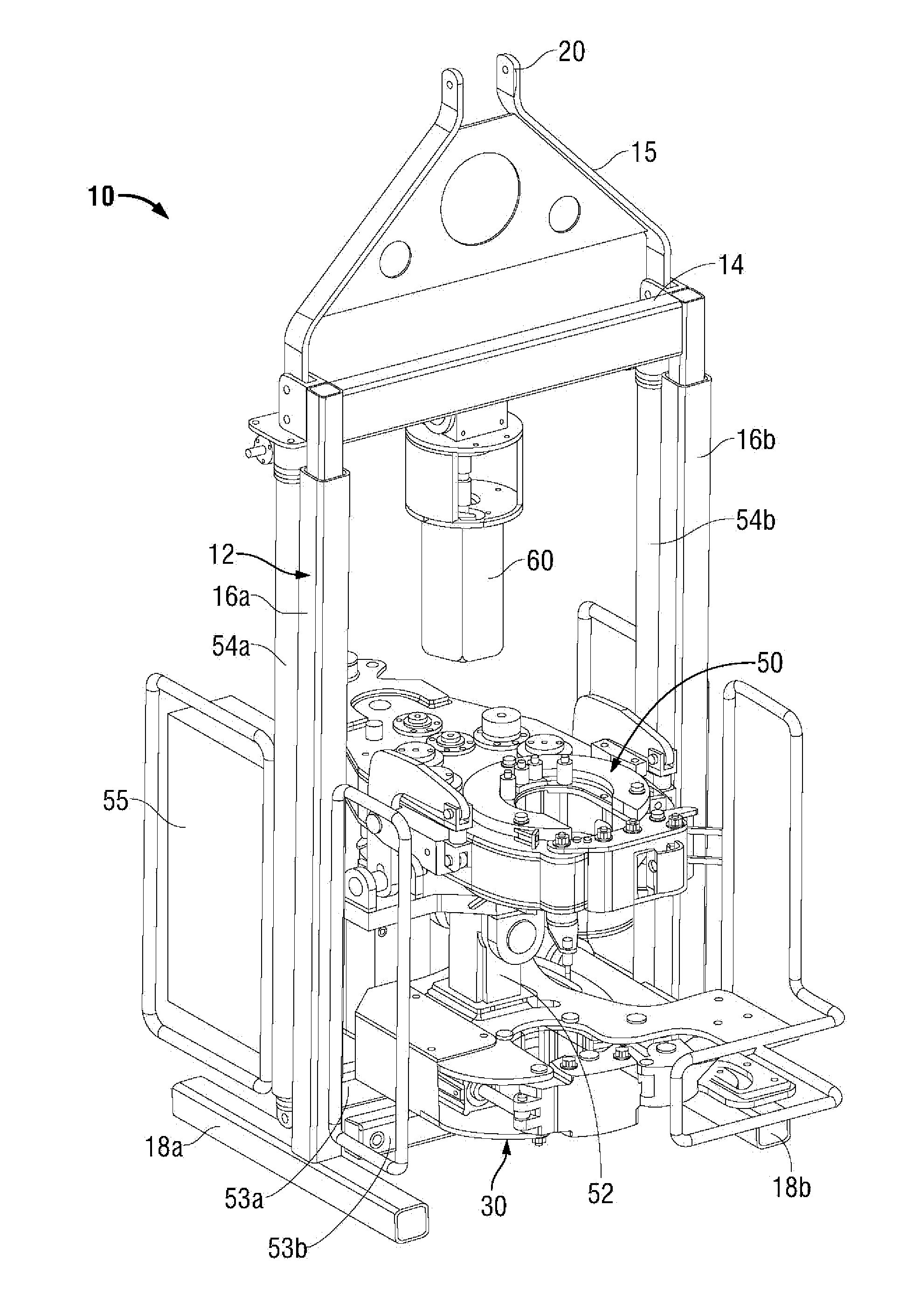
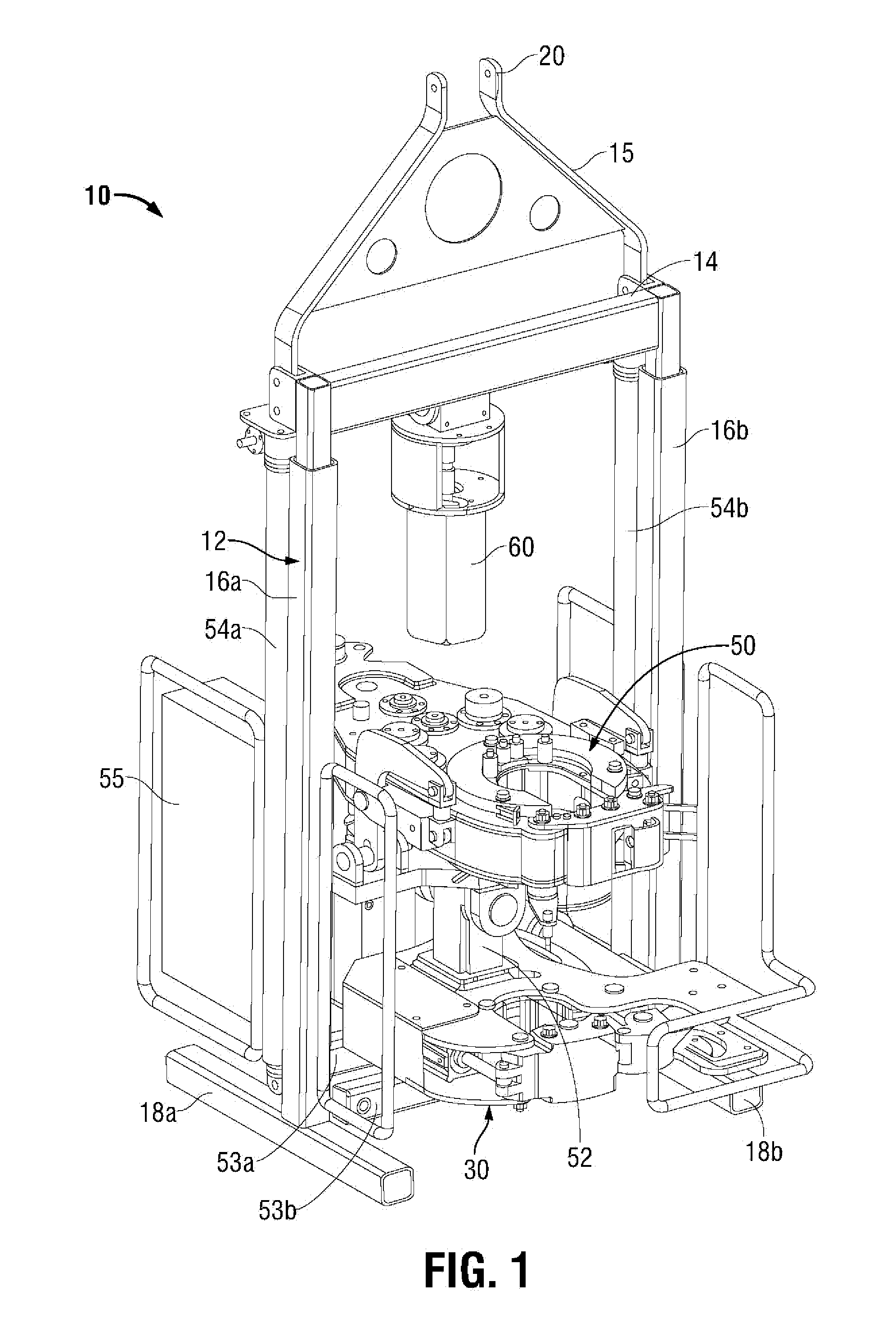
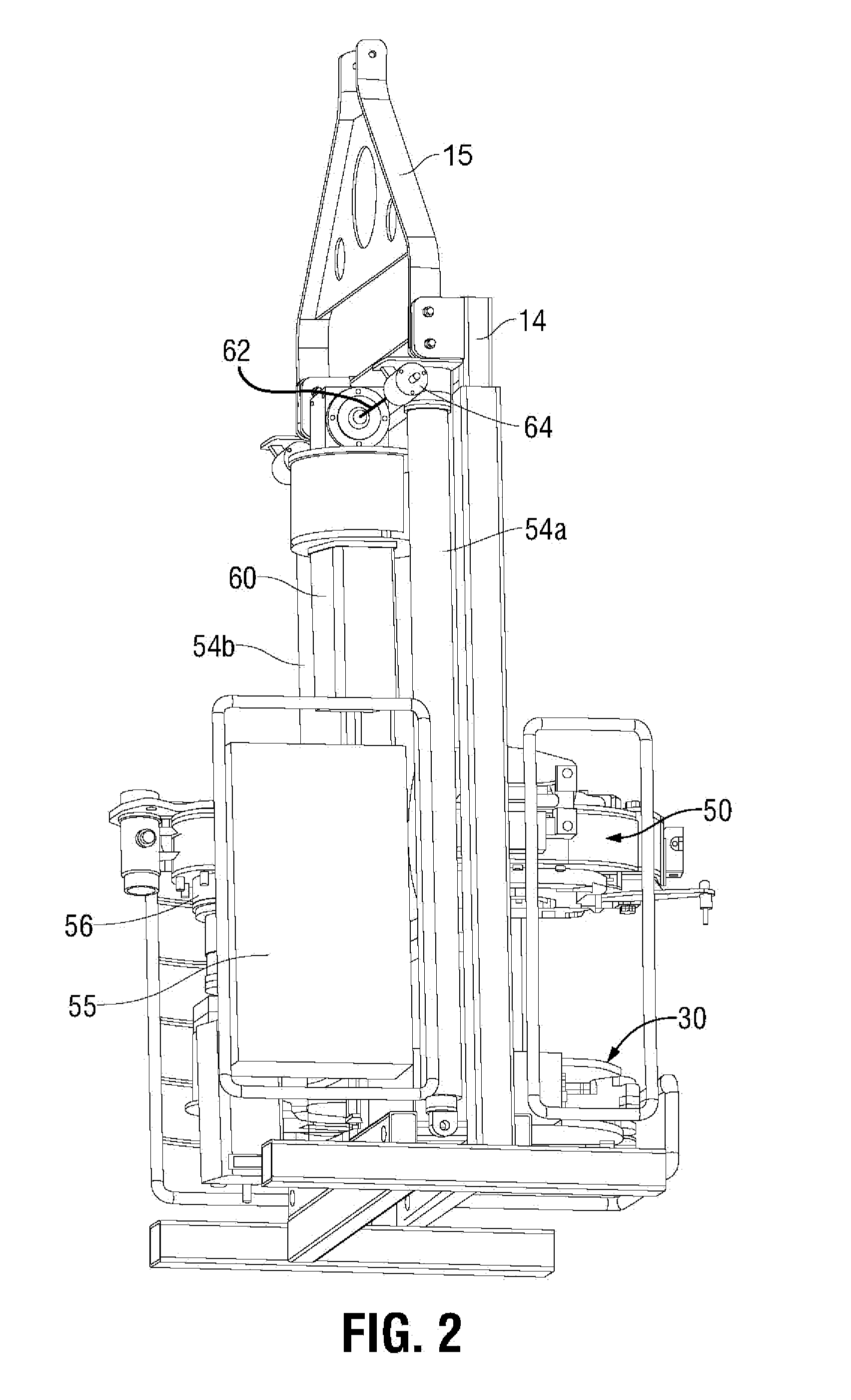
An automated, electric tong system and methods usable for making-up and breaking out threaded connections between tubular members, wherein the electric tong system comprises a power tong for applying torque and rotating the upper tubular member, a backup tong for gripping tubulars, and a lift assembly for vertically moving the electric tong system into proper position to grip the upper and lower tubulars. The power and backup tongs and lift assembly of the electric tong system are integrated into a single transportable unit and operated by three separate electrical motors, controlled by a single driver. The backup tong is located below the power tong and comprises a pneumatic cylinder, which operates a backup door, and a linear actuator driven by an electric motor for use in latching the backup tong door in a closed position and applying or releasing a clamping force to a tubular, during make-up or break-out operations.

Description

CROSS-REFERENCE TO RELATED APPLICATION[0001]The present application is a non-provisional application that claims priority to a U.S. Provisional Application having U.S. Patent Application Ser. No. 61 / 893,819, filed Oct. 21, 2013, and U.S. Provisional Application having U.S. Patent Application Ser. No. 62 / 001,500, filed May 21, 2014, both of which are incorporated herein in their entireties by reference.FIELD[0002]Embodiments of the present disclosure relate, generally, to apparatus and methods for making up and breaking out wellbore tubulars and, more particularly, to an integrated, electric tong system and methods of use at a wellbore.BACKGROUND[0003]In the oil and gas industry, oil field tools, such as tongs or wrenches, are used to grip and rotate joints of tubulars (e.g., casing, drill pipe, other tubulars), particularly during makeup operations (e.g., threadably engaging, screwing together) or break-out operations (e.g., threadably disengage, unscrew). These oil field operations...

Claims


Application Information

Patent Timeline
Patent Type & Authority Applications(United States)
IPC IPC(8): E21B19/16
CPCE21B19/164E21B19/165
Inventor MOSING, DONALD E.BOULIGNY, VERNON J.
Owner FRANKS INT
Why Eureka
Try Eureka