Flourescent lamp socket with enhanced contact reliability

a technology for fluorescent lamps and sockets, applied in the field of lampsockets, can solve the problems of reducing contact forces, lamp not being rotated into the correct contact position, and large force required to rotate fluorescent lamps, and achieve the effect of large compression forces

Inactive Publication Date: 2009-08-04
VOSSLOH SCHWABE DEUT GMBH
View PDF9 Cites 20 Cited by
  • Summary
  • Abstract
  • Description
  • Claims
  • Application Information

AI Technical Summary

Benefits of technology

[0004]It is the object of the invention to create a lamp socket with enhanced reliability.
[0006]The lamp socket according to the invention demonstrates a housing made of insulating material and at least one contact mounted in the housing and a rotor, which is rotatably mounted and consists of insulating material. A support means for the rotor is disposed on the rotor. While the contact is held in the housing, the support means rotates along with the rotor. It therefore moves relative to the housing and to the contact. This circumstance can be utilized to allow the support of the contact to become effective only when the lamp has been rotated into connected position. When the lamp is not in its connected position but in its insertion position, the support means can be ineffective. In other words, the support means can be used to press the contact onto the pin of the lamp when the lamp is rotated into contact position. This makes it possible to create a lamp socket that achieves a high contact force with relatively flexible contacts. Due to the high contact force, a lower electrical transition resistance arises between the contact and the pin of the lamp. The danger of heating or overheating the contact is excluded.
[0008]It is advantageous if the lamp socket is provided with a pin support device, which can be disposed between the pins of the lamp for example. This makes it possible to let relatively large compression forces act between the contact and the pin of the lamp without overloading the pin of the lamp.
[0009]It is furthermore advantageous if a stopping means is provided opposite the support means. The stopping means can, for example, be a projection, which is provided on the rotor and which defines a slot or passage in combination with the support means. Whereas the support means is configured as an arc-shaped rib, for example, a triangular nose or the like can form the stopping means. The stopping means can be used to keep the contact from being too far radially inwards when the rotor is in the lamp insertion position. Finally, a rotor is thereby created which actively moves the contact from a radially further outward position when the rotor is in the lamp insert position to a radially further inward position when the rotor is in connected position.

Problems solved by technology

The forces required to rotate the fluorescent lamp are correspondingly large, a fact that can result in the lamp not being rotated into its correct contact position of, for example, a 90° twist relative to the insertion position, during the installation.
Such a case can lead to diminished contact forces, and consequently to increased transition resistances and ultimately to impermissible heating.

Method used


Image

  • Flourescent lamp socket with enhanced contact reliability
  • Flourescent lamp socket with enhanced contact reliability
  • Flourescent lamp socket with enhanced contact reliability

Examples


Embodiment Construction

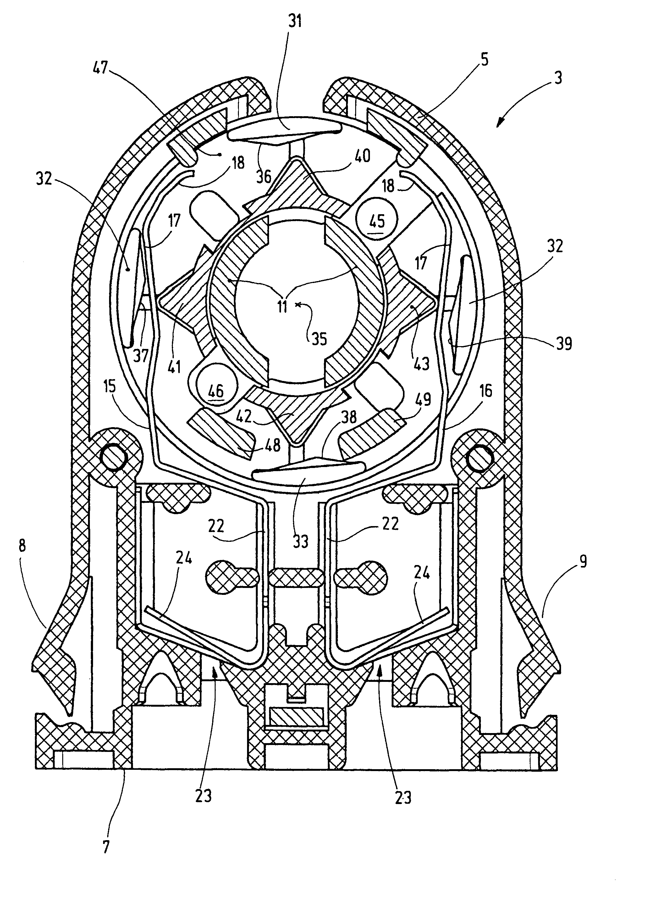
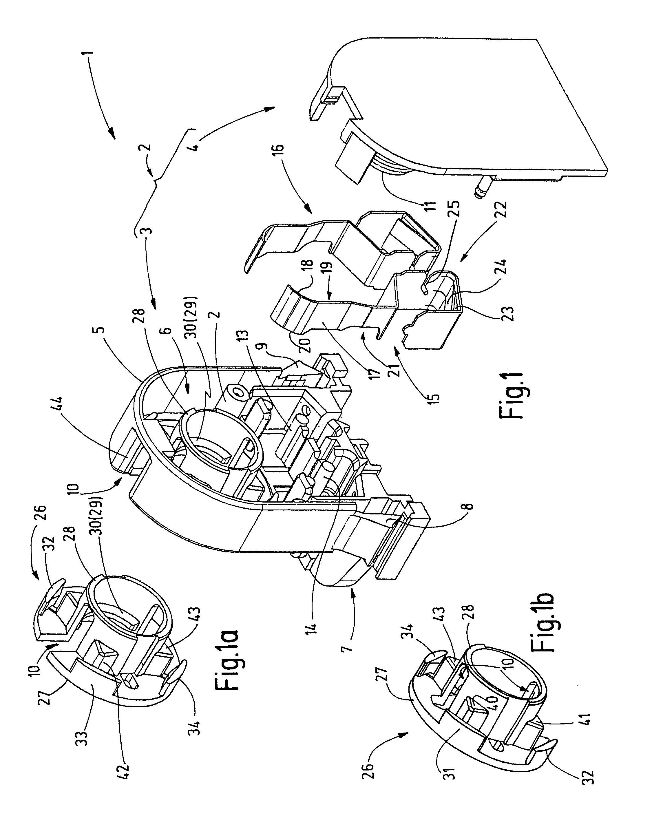
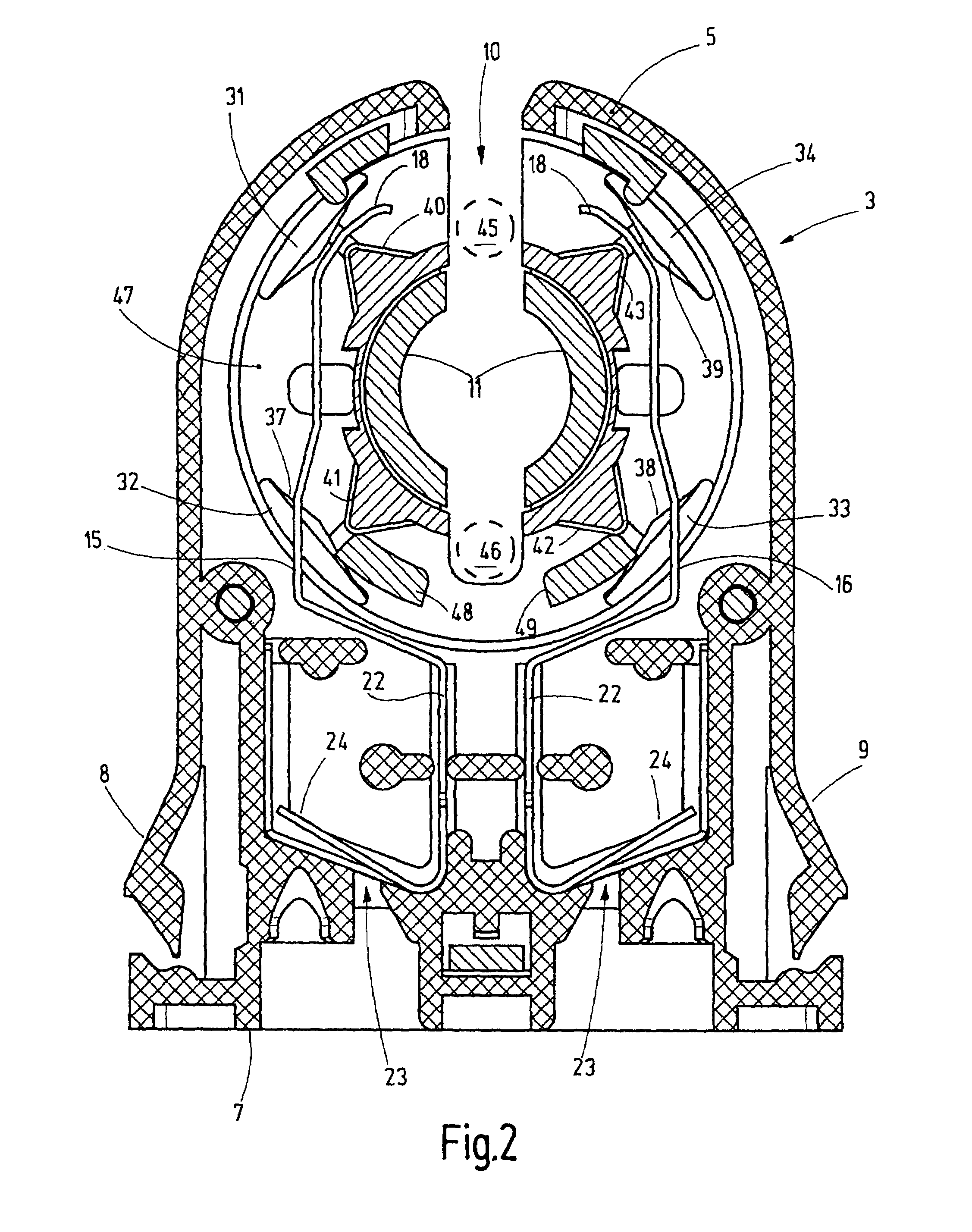
[0017]The lamp socket 1 illustrated in FIG. 1 demonstrates a housing 2, which is made of insulating material and can comprise of two housing parts 3, 4 for example. The housing parts 3, 4 consist of an insulating material, such as an injection moldable plastic. Whereas the housing part 4 forms a basically flat back wall, a plurality of projections projecting from its flat side, housing part 3 is provided with a U-shaped rim 5, which projects from a front side and defines an interior space 6. One or more feet 7, which serve to fasten the lamp socket 1 to a trunking or other carrier, are provided on one end of housing part 3, it also being possible to provide latches 8, 9.

[0018]The housing part 3 is provided with an insertion slot 10, which passes through the rim 5 and the front side of the housing part 3. To this end, the insertion slot 10 also crosses a pipe-socket-like catch 11, which projects from the front side of the housing part 4 into its interior space 6. Additional extension...


PUM


Abstract

The lamp socket according to the invention demonstrates a housing (2) with a rotor (26). Contacts (15, 16), which demonstrate contact tags (17) that are resilient in the swivel direction, are mounted in the housing (2). The open ends (18) of the contact tags can support themselves on stopping means (31 to 34), which are moved by the rotor (26). In the support position, they are positioned on the ends (18) of the contacts (15, 16). When the lamp is rotated from its insertion position into its connected position, the support means (31 to 34) are distant from the ends (18) of the contacts (15, 16), however, so that the lamp can be rotated relatively freely without current. Only near the end of this rotational movement do cams provided on the support means (31 to 34) bump against the ends (18) of the contacts (15, 16) and force them radially inwards and clamp the contacts (15, 16) against the pins (45, 46) of the lamp.

Description

BACKGROUND OF THE INVENTION[0001]The invention relates to a socket for lamps, especially electric discharge lamps, preferably fluorescent lamps.SUMMARY OF THE INVENTION[0002]Fluorescent lamps often consist of a straight discharge tube which is provided with a socket at both ends. Each socket carries two pins, which serve for mechanical mounting of the fluorescent lamp and for the electrical supply of same. Various lamp sockets for such fluorescent lamps are in use. One example for this can be found in EP 1 251 603 A2. The lamp socket illustrated therein demonstrates a housing made of insulating material into which a rotor, likewise consisting of insulating material, is inserted. The rotor can rotate around an axis that is coaxial to the lamp tube of the fluorescent lamp accommodated by the socket. The rotor is provided with an insertion slot, into which the pins of the fluorescent lamp can be inserted in the radial direction. Springy contact sheets, which come into contact with the ...

Claims


Application Information

Patent Timeline
Patent Type & Authority Patents(United States)
IPC IPC(8): H01R33/02
CPCH01R33/0854H01R33/0827
Inventor BRAND, ANDREASSELVE, ULF
Owner VOSSLOH SCHWABE DEUT GMBH
Why Eureka
Try Eureka