Method and apparatus for preventing the friction induced rotation of non-rotating stabilizers

a non-rotating stabilizer and friction induced technology, which is applied in the direction of drilling rods, drilling casings, drilling pipes, etc., can solve the problems of low curvature rate and/or low bit weight, preventing the use of conventional rotary steerable systems on many directional drilling applications, and high frictional rotation ra

Inactive Publication Date: 2005-07-14
VALIDUS
View PDF10 Cites 19 Cited by
  • Summary
  • Abstract
  • Description
  • Claims
  • Application Information

AI Technical Summary

Problems solved by technology

However, rotation rates may become excessive at low hole angles, low curvature rates and / or low bit weights.
This problem prevents the use of conventional rotary steerable systems on many directional drilling applications.
Even with a hole angle of 30 degrees the expected frictional rotation rates would be a problem.
With a 0.5 degree hole angle, the rotation rates are unacceptable.

Method used


Image

  • Method and apparatus for preventing the friction induced rotation of non-rotating stabilizers
  • Method and apparatus for preventing the friction induced rotation of non-rotating stabilizers
  • Method and apparatus for preventing the friction induced rotation of non-rotating stabilizers

Examples


Embodiment Construction

[0011] Referring to the accompanying Figures, a preferred embodiment of the invention is described as follows.

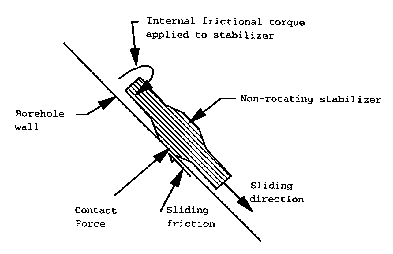
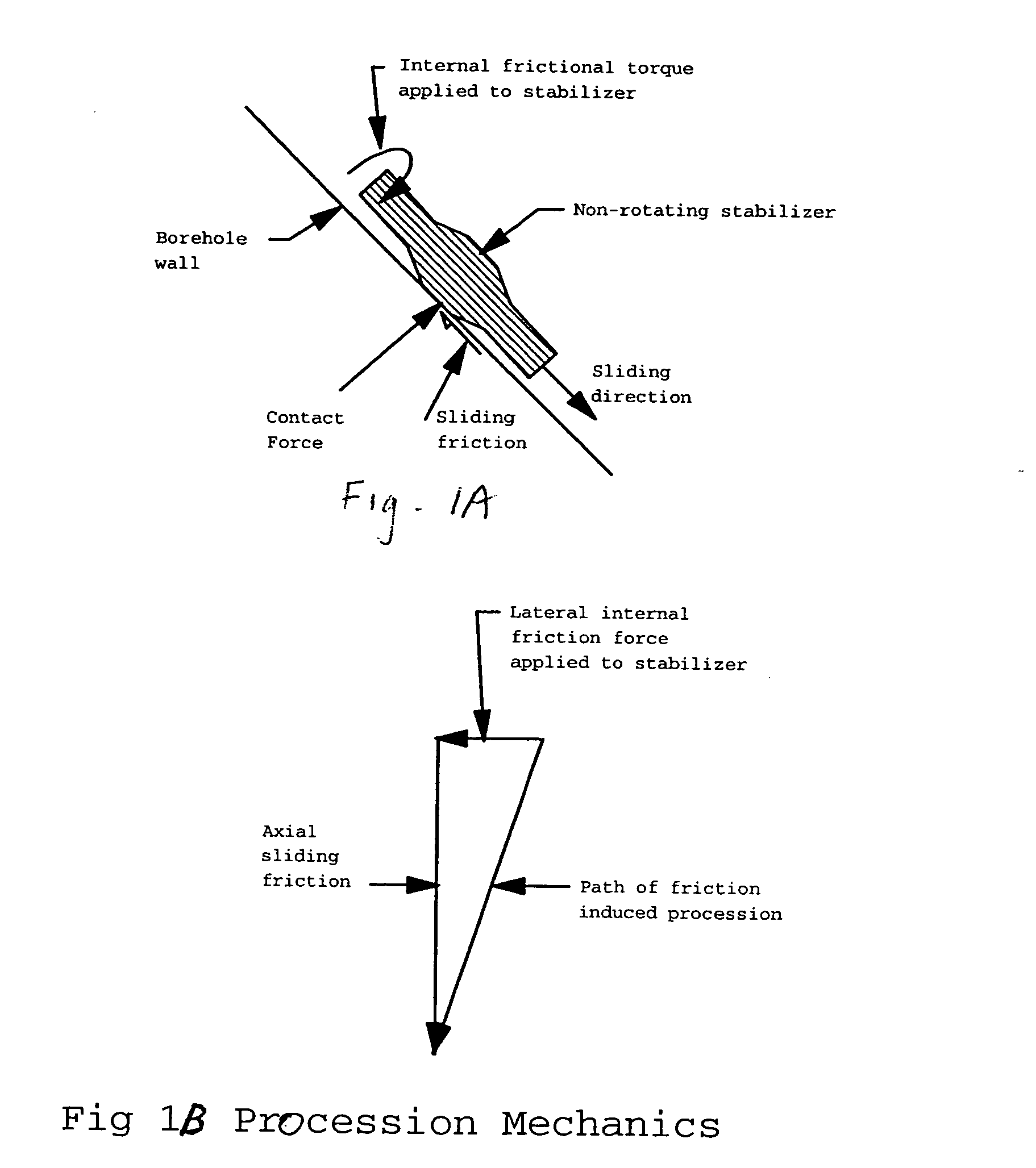
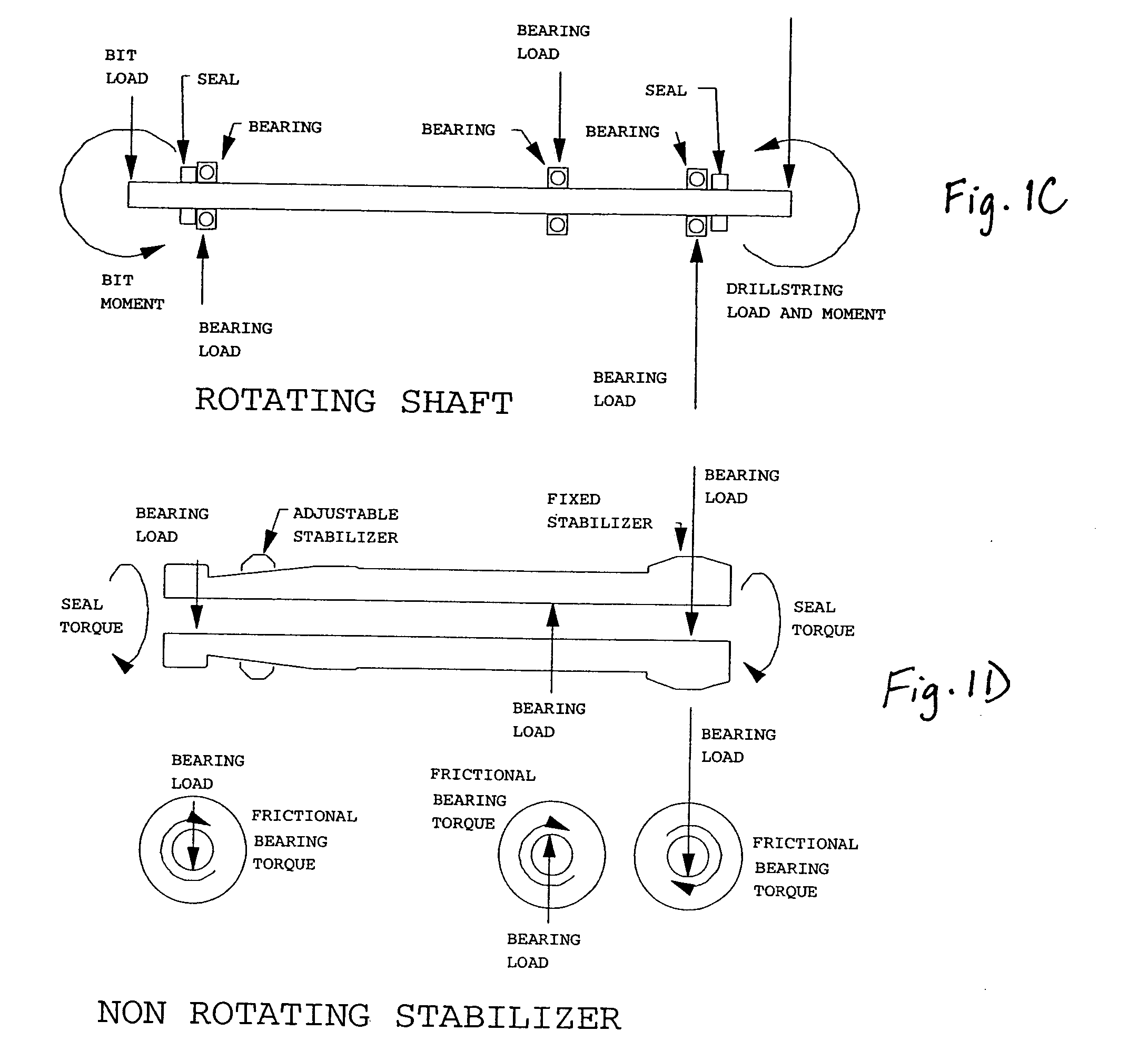
[0012] Referring to FIGS. 1A-1D, the present inventor determined that the mechanics of frictional rotation are defined generally by the following equations: RDT=bd·ff·SBF2+2·st(1)

[0013] Where:

RDT = Rotational driving torquein lbs.bd = Shaft bearing diameterin.ff = Bearing friction factor*SBF = Sum of all the bearing forceslbs.st = Rotating seal torquein lbs

[0014] The present invention is specifically applicable to drilling tools including two to four bearings. However, the invention may be applied to a drilling tool with a different number of bearings as long as the summation of the lateral forces on the bearings (SBF) is taken into account. The rotational driving torque comes from the frictional torque in the Kalsi seals and the lateral contact forces in the bearings between the shaft and the (non-adjustable stabilizer) (NAS). The resisting forces are generated by the l...


PUM


Abstract

A method and apparatus prevents rotation of a stabilizer which rotates due to friction-induced forces of bearing seals disposed in a shaft. The apparatus includes a stabilizer having a ridged edge where the stabilizer is mounted to a drilling tool using a deformable member. The deformable member assists in creating friction of the stabilizer edge against a drilled bore hole wall and thereby reduces friction-induced rotation.

Description

FIELD OF THE INVENTION [0001] This invention provides a novel method and apparatus for preventing the friction induced rotation of non-rotating stabilizers which are attached to a drilling tool to control the direction and orientation of drilling. The invention can be utilized to prevent rotation at any combination of hole angle, curvature rate and bit load. The present invention provides a more efficient method of operating rotary steerable directional tools. BACKGROUND [0002] Most rotary steerable systems utilize non-rotating stabilizers to control the trajectory of the hole. The rotating friction between the non-rotating stabilizer and the shaft that turns the bit on conventional systems causes the non-rotating stabilizer to rotate in a clockwise direction. With conventionally surfaced stabilizers, the procession rate is related to the ratio of the rotational friction force between the shaft and the fixed stabilizer to the axial drag force between the fixed stabilizer and the bor...

Claims


Application Information

Patent Timeline
Patent Type & Authority Applications(United States)
IPC IPC(8): E21B17/10
CPCE21B17/1057
Inventor SCHUH, FRANK J.
Owner VALIDUS
Why Eureka
Try Eureka