Segmented component seal

a technology of components and seals, applied in the field of segmented component seals, can solve the problems of premature oxidation of components, cracks, and increase the fuel burn of engines

Active Publication Date: 2007-09-13
RAYTHEON TECH CORP
View PDF19 Cites 18 Cited by
  • Summary
  • Abstract
  • Description
  • Claims
  • Application Information

AI Technical Summary

Benefits of technology

[0012] In accordance with the present invention, there is provided a seal for restricting leakage of a hig

Problems solved by technology

Because stationary components such as vanes, shrouds, supports and the like are subject to extreme temperature gradients, they can develop cracks due to thermal mechanical fatigue (TMF).
Excessive leakage of the compressor air may cause premature oxidation of the components and can increase the engine's fuel

Method used


Image

  • Segmented component seal
  • Segmented component seal
  • Segmented component seal

Examples


Embodiment Construction

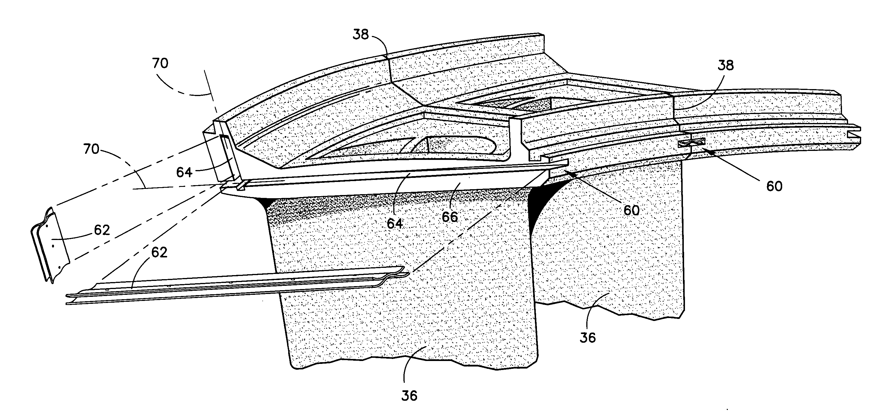
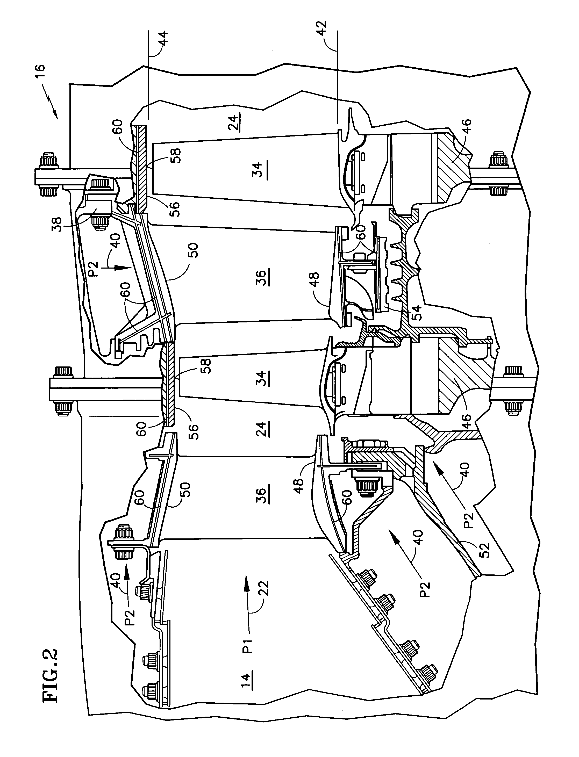
[0023] An exemplary turbine 16 of a gas turbine engine 10 is illustrated in FIG. 2. The high temperature combustion gases 22 discharge rearward from the combustor 14, at a pressure (P1), to an annular duct 24 defined by an inner periphery 42 and an outer periphery 44. Stationary vanes 36 guide the combustion gases 22 to rotating blades 34, extending radially outwardly from rotor disks 46. The vanes 36 span radially between inner 48 and outer 50 shrouds, which are suspended from an inner support 52 and / or outer casing 38 structures. Inner seals 54 restrict leakage of the combustion gases 22 from radially beneath the vanes 36 at the inner periphery 42. Outer seals 56 restrict leakage of the combustion gases 22 from radially above tips 58 of the blades 34 at the outer periphery 44.

[0024] Those skilled in the art will appreciate that each of the above-described components must be actively cooled, because the combustion gas 22 temperature typically exceeds the melting temperatures of th...


PUM


Abstract

A seal for restricting leakage of a fluid from a first chamber, through a gap between two components, to a second chamber is provided. A slot is formed in each of the two components. The slots face one another and are open to the gap. Each slot contains a longitudinal axis, an upstream surface proximate the first chamber and a downstream surface proximate the-second chamber. Disposed in the slots and spanning the gap is a bridging assembly comprising first and second bridging elements. Each bridging element contains a sectional profile, transverse to the longitudinal slot axis, that is wave shaped. The bridging elements further contain a crest portion disposed between two trough portions with the crest portions nesting together. When installed, the trough portions are disposed in the slots and the crest portions are disposed in the gap.

Description

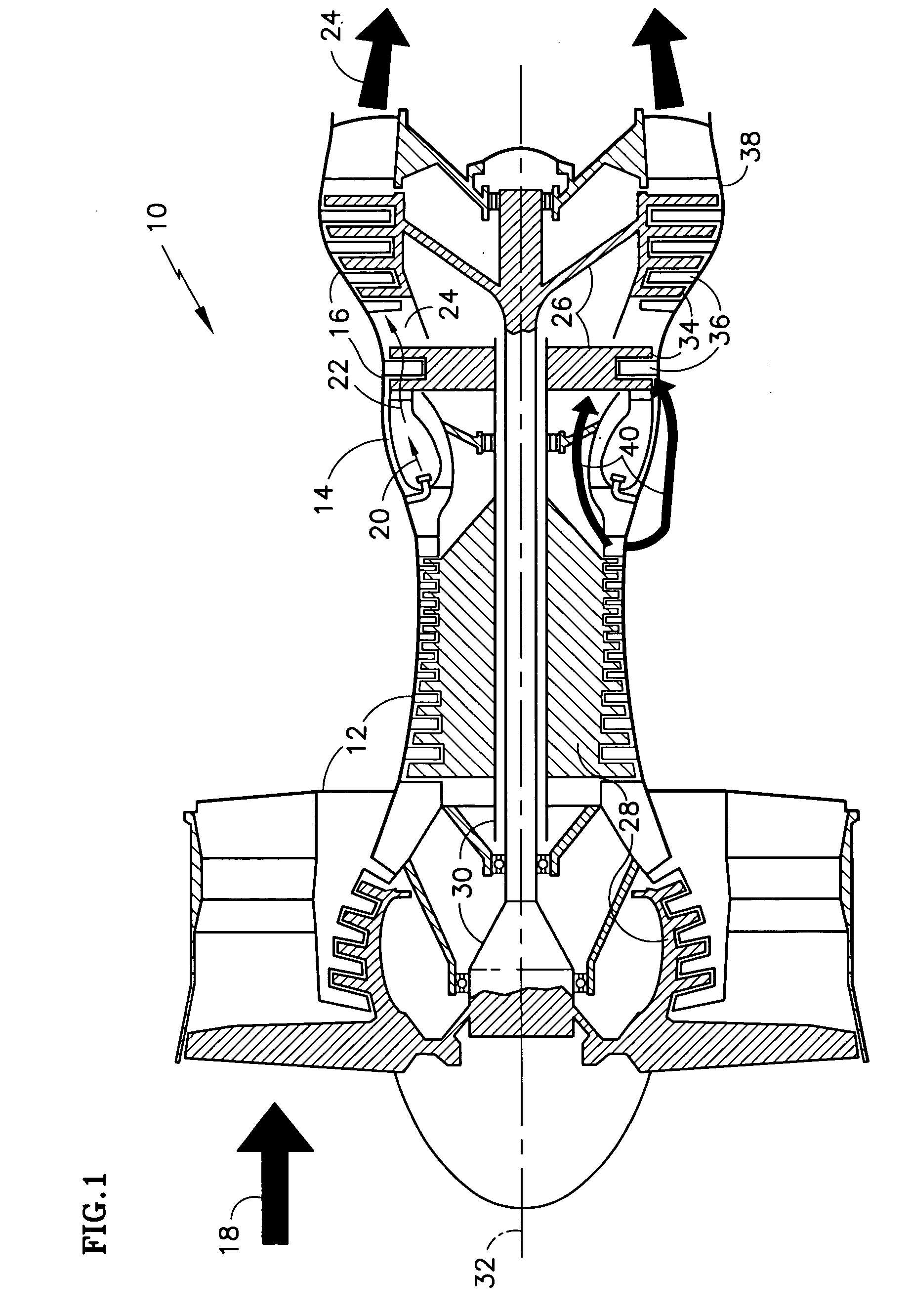
BACKGROUND OF THE INVENTION [0001] (1) Field of the Invention [0002] The invention relates to gas turbine engine components in general, and specifically to a seal for preventing leakage of high pressure air or other fluids between segmented components used in such engines. [0003] (2) Description of the Related Art [0004] As illustrated in FIG. 1, a gas turbine engine 10 comprises one or more forward compressor sections 12, a central combustor section 14 and one or more rearward turbine sections 16. The engine 10 operates by compressing ambient air 18 with the compressors 12, adding fuel upstream of the combustor 14 and burning a fuel-air mixture 20 in the combustor 14. High temperature combustion gases 22 are directed axially rearward from the combustor 14, through an annular duct 24 disposed in the turbines 16. The combustion gases 22 interact with one or more turbine rotors 26, outer portions of which are disposed in the duct 24. The turbine rotors 26 are coupled to compressor rot...

Claims


Application Information

Patent Timeline
IPC IPC(8): F16J15/02
CPCF01D11/005F01D11/008F05D2250/611F05D2240/11F05D2240/57F16J15/0887
Inventor PAAUWE, COMEIL
Owner RAYTHEON TECH CORP
Why Eureka
Try Eureka