Saber saw tool

Active Publication Date: 2005-12-01
HILTI AG
View PDF15 Cites 17 Cited by
  • Summary
  • Abstract
  • Description
  • Claims
  • Application Information

AI Technical Summary

Benefits of technology

[0010] It is particularly advantageous, if the angle α between the guide of the mass equilibrating body and the stroke driving means lie

Problems solved by technology

However, stroke driving means and mass equilibration bodies

Method used


Image

  • Saber saw tool
  • Saber saw tool
  • Saber saw tool

Examples


Embodiment Construction

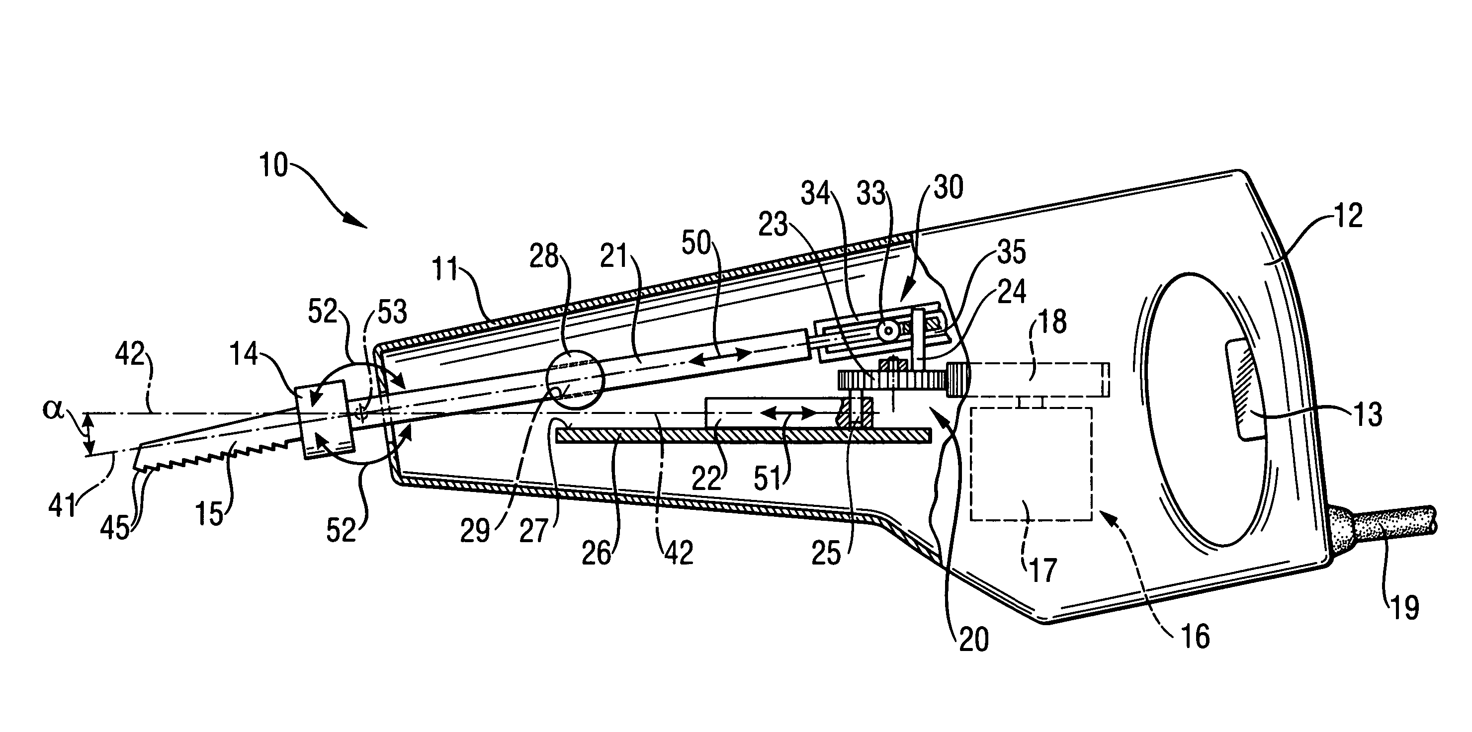
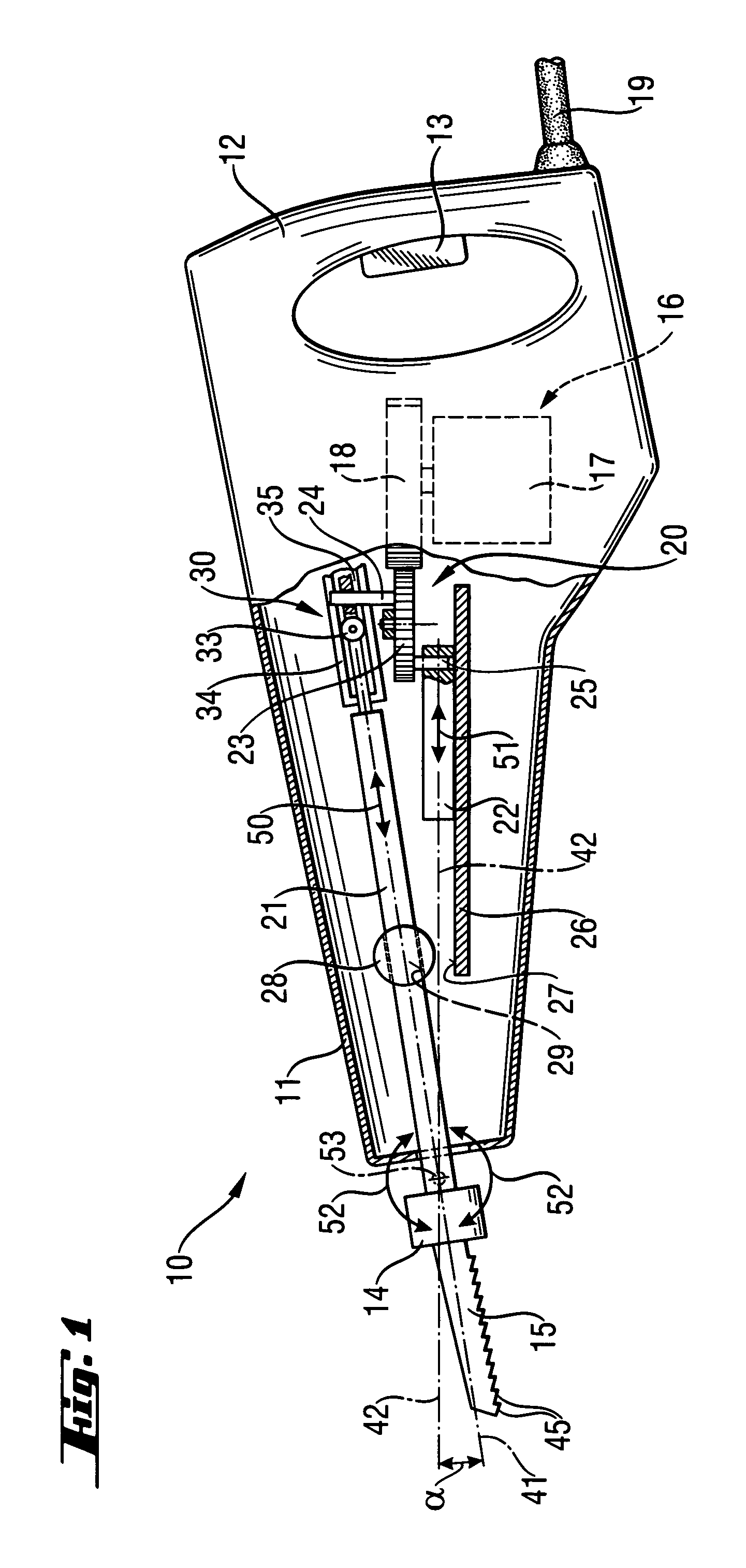
[0014]FIGS. 1 and 2 represent a reciprocating saw tool 10 configured as a saber saw, wherein a driving arrangement is arranged in a single- or multiple-part housing 11. The driving arrangement 16 comprises a motor drive 17 such as an electrical motor and a device 20 for converting a rotary movement of the motor drive 17 into a reciprocating movement of a reciprocating drive means 21 along a first axis of movement 41 and a reciprocating movement of the mass equilibrating body 22 moving in the opposite direction along a second axis of movement 42. The power supply of the reciprocating saw tool 10 uses a mains connection 19 such as a power cable that can be connected to a power supply. Alternatively, a storage battery or a battery array, etc. can be used for providing power to the reciprocating saw tool.

[0015] Furthermore, a handle 12 is formed on the reciprocating saw tool 10 on which a switching means 13 is provided for actuating the reciprocating saw tool 10. A tool holder 14 at wh...


PUM

PropertyMeasurementUnit
Angleaaaaaaaaaa
Angleaaaaaaaaaa
Angleaaaaaaaaaa

Abstract

The present invention relates to a reciprocating saw tool (10) having a motor drive (17) with a reciprocating driver (21) for a tool (15) and having a mass equilibrating body (22). In addition, a device (20) is provided, which serves to convert a rotary movement of the motor drive (17) into a reciprocating movement of the reciprocating driver (21) along a first movement axis (41) and an opposite reciprocating movement of the mass equilibrating body (22) along a second movement axis (42). For improving the sawing performance, the mass equilibrating body (22) is guided at an angle α to the reciprocating driver (21) so that its movement axis (42) is constantly at an angle to the movement axis (41) of the reciprocating driver (21).

Description

BACKGROUND OF THE INVENTION [0001] The present invention relates to a saber saw tool having a motor drive with a reciprocating driver means for a tool having a mass equilibrating body and a device for converting a rotary movement of the motor drive into a reciprocating movement of the reciprocating means along a first movement axis and an opposite movement axis. In this tool the mass equilibrating body is guided at an angle α to the reciprocating driver means such that the movement axis runs constant at an angle to the movement axis of the reciprocating driver means. This type of saber saw tool is a saber saw or a jigsaw, wherein a saw blade can be displaced in a reciprocating movement using a driving arrangement. [0002] In saber saw tools a counterweight is provided for balancing the unbalance of the reciprocating means such as a stroke rod, which is operated with the reciprocating means in the direction opposite to the drive train. [0003] U.S. Pat. No. 6,634,107 discloses this typ...

Claims


Application Information

Patent Timeline
IPC IPC(8): B23D49/04B23D49/16B23D51/16B23D51/20B27B3/12B27B11/00B27B19/02B27B19/09
CPCB23D51/16B23D49/165
Inventor HAAS, GUENTERWIDMER, LOUIS
Owner HILTI AG
Why Eureka
Try Eureka