Vacuum evaporation deposition method of the winding type and vacuum evaporation deposition apparatus of the same

a vacuum evaporation deposition and winding type technology, which is applied in the direction of electric/magnetic/electromagnetic heating, solid-state diffusion coating, instruments, etc., can solve the problems of deteriorating contact force, inconvenient metal film deposition on the prior art apparatus, and inability to apply bias potential to the base film before metal film deposition, etc., to achieve high contact force, prevent thermal deformation of insulating material film, and improve film-running speed and productivity

Inactive Publication Date: 2007-06-14
ULVAC INC
View PDF6 Cites 19 Cited by
  • Summary
  • Abstract
  • Description
  • Claims
  • Application Information

AI Technical Summary

Benefits of technology

[0018] According to this invention, a high contact force can be obtained between the insulating material base film and the cooling roller, both before and after the deposition of metal film. Thus, the thermal deformation of the insulating material film can be prevented. The film-running speed and the productivity can also be improved.

Problems solved by technology

There is a problem that the prior art apparatus is not suitable for metal film deposition on a base film such as plastics.
However, when a metal film is newly deposited, the bias potential cannot be applied to the base film before the metal film deposition.
In that case, the electro-static attractive force is lowered between the can roller and the material film and so the contact force is deteriorated.
Accordingly, the charge method and the bias application method employed in the prior art deposition apparatus of the winding type are not suitable for metal film deposition on the base film such as plastic film, and a high contact force cannot be obtained between the cooling can roller and the metal film.
The base film is shrunk and deformed due to the deficiency of the cooling effect of the base film.
Accordingly, the productivity cannot be improved.

Method used


Image

  • Vacuum evaporation deposition method of the winding type and vacuum evaporation deposition apparatus of the same
  • Vacuum evaporation deposition method of the winding type and vacuum evaporation deposition apparatus of the same
  • Vacuum evaporation deposition method of the winding type and vacuum evaporation deposition apparatus of the same

Examples


Embodiment Construction

[0040] Next, an embodiment of this invention will be described with reference to the drawings.

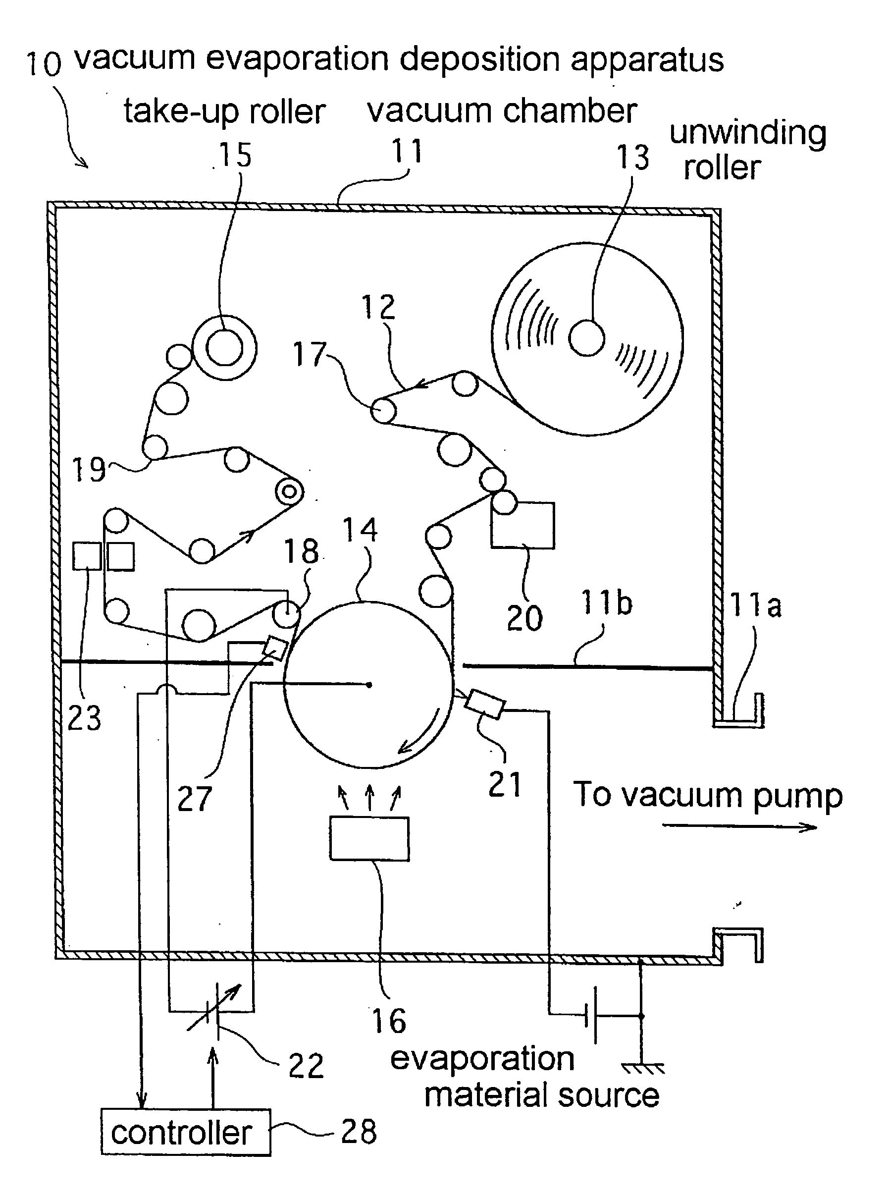
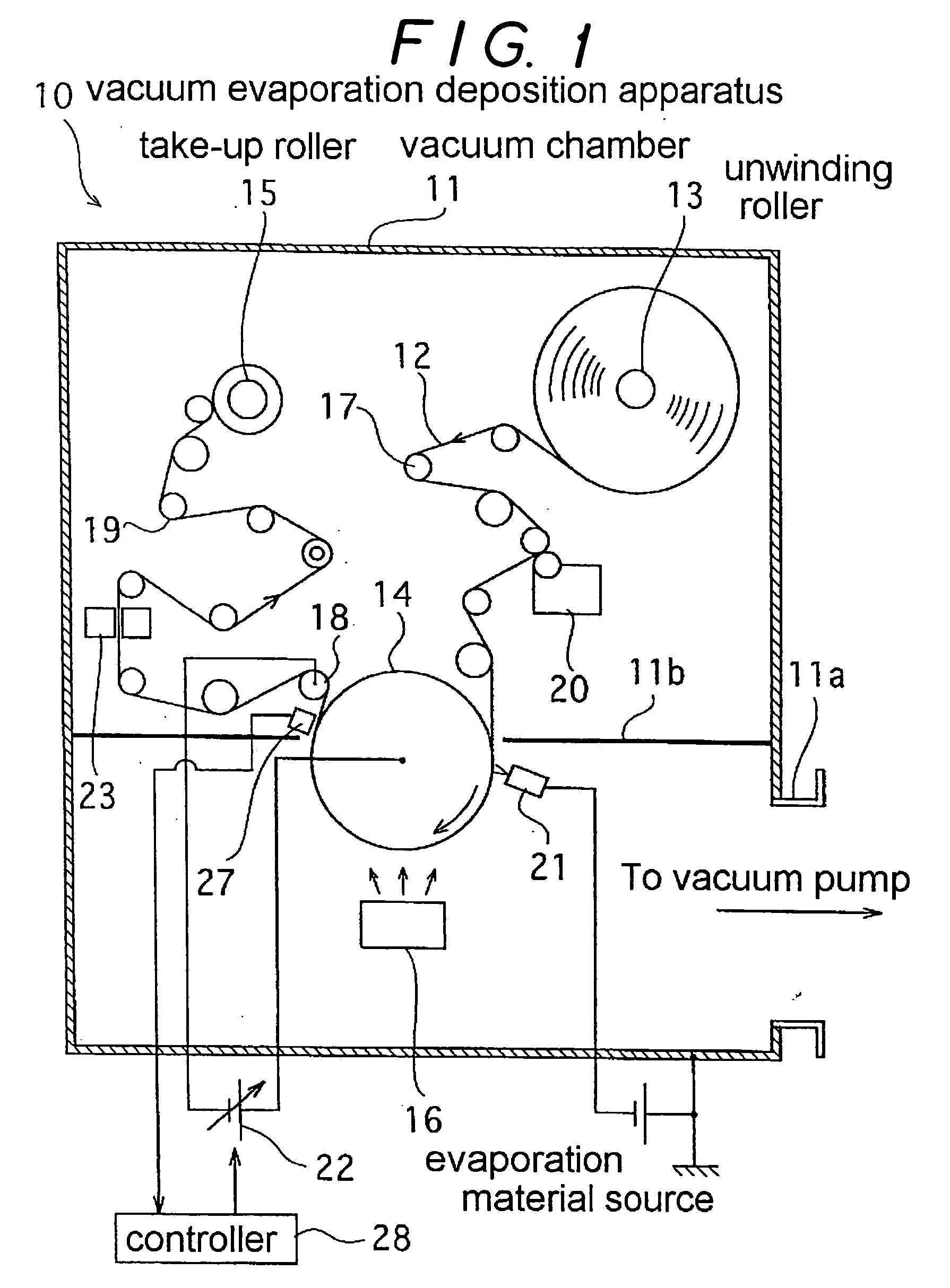
[0041]FIG. 1 is a schematic view of a vacuum evaporation deposition apparatus of the winding type according to an embodiment of this invention. The vacuum evaporation deposition apparatus 10 of the winding type according to this embodiment is provided with a vacuum chamber 11, an unwinding roller 13 for an insulating material base film 12, a cooling can roller 14, a take-up roller 15 and an evaporation deposition source 16 of material to be deposited.

[0042] The vacuum chamber 11 is connected through a conduit portion 11a to a vacuum exhaust system including a vacuum pump (not shown). The interior of the vacuum chamber 11 is exhausted to a predetermined pressure and it is partitioned into two chambers by a partition wall 11b. The unwinding roller 13 and take-up roller 15 are arranged in the one of the chambers and the evaporation source 16 is arranged in another of the chambers.

[0043] The...


PUM

PropertyMeasurementUnit
DC bias voltageaaaaaaaaaa
scanning frequencyaaaaaaaaaa
pressureaaaaaaaaaa

Abstract

The invention provides a vacuum evaporation deposition method of the winding type and a vacuum evaporation deposition apparatus of the winding type which can form a metal film on a base film made of a single layer of insulating material such as plastic film without thermal deformation, and which is superior in productivity. An electron beam irradiator 21 irradiates an electron beam onto an insulating material base film 12 before deposition of metal, and a DC bias power source 22 applies bias voltage between an auxiliary roller 18 for guiding the base film 12 with metal film deposited thereon and a can roller 14, whereby the base film 12 charged by the irradiation of the electron beam before the deposition of metal film, is made to be in close contact with the can roller 14. The base film 12 after deposition of metal film is made to be in close contact with the can roller 14 by the bias voltage applied between the auxiliary roller 18 connected electrically to the metal film and the can roller 14.

Description

TECHNICAL FIELD [0001] This invention relates to a vacuum evaporation deposition method of the winding type in which an insulting base film is continuously dispensed in a reduced pressure atmosphere, and cooled by a cooling roller in close contact, and a metal film is deposited on the insulating film and the metal-deposited film is wound up on a take-up roller. BACKGROUND OF THE TECHNIQUE [0002] In the prior art, such an evaporation deposition method of the winding type is known in which a long base film of insulating material is continuously dispensed from a dispense roller, passed along in contact with a cooling can roller and evaporation material from an evaporation source facing to the can roller is deposited on the base film, and the deposited base film is wound up on a take-up roller. That method is disclosed, for example, in the following patent literature 1. [0003] In the vacuum evaporation deposition method of this kind, a base film of insulating material is cooled in conta...

Claims


Application Information

Patent Timeline
Patent Type & Authority Applications(United States)
IPC IPC(8): B05D3/00C23C8/00H05B6/02C23C16/00B29C71/04C23C14/02C23C14/14C23C14/56G11B5/85
CPCC23C14/022C23C14/562G11B5/85
Inventor HAYASHI, NOBUHIROHIRONO, TAKAYOSHITADA, ISAONAKATSUKA, ATSUSHI
Owner ULVAC INC
Why Eureka
Try Eureka