
Mechanical manipulator for surgical instruments

a mechanical manipulator and surgical instrument technology, applied in mechanical apparatus, surgical forceps, gearing, etc., can solve the problems of high acquisition and maintenance costs, non-ergonomic, non-intuitive and missing in adequate stiffness, precision and force feedback, and difficulty in learning and performing such procedures with current laparoscopic equipment. , to achieve the effect of high payload capacity, high payload capacity, and high dexterity

Active Publication Date: 2018-10-09
ECOLE POLYTECHNIQUE FEDERALE DE LAUSANNE (EPFL)
View PDF361 Cites 21 Cited by
  • Summary
  • Abstract
  • Description
  • Claims
  • Application Information

AI Technical Summary

Benefits of technology

The present invention provides a new cable-based mechanical system that can be used to actuate multi-DOF micro-manipulators. This system offers dexterity, stiffness, speed, precision, and payload capacity. It combines the benefits of conventional laparoscopy, single port surgery, and robotic surgery. Increasing the number of cable turns around the idler tubes can increase the contact force.

Problems solved by technology

However, from the surgeon's point of view, there are still many difficulties in learning and performing such procedures with current laparoscopic equipment, which is non-ergonomic, non-intuitive and missing in adequate stiffness, precision and force feedback.
A major disadvantage of these systems is the high cost of acquisition and maintenance which are actually not affordable for the majority of surgical departments worldwide.
Another drawback of these systems is related with the fact that current surgical robots are voluminous, competing for precious space within the operating room environment and significantly increasing preparation time.
Access to the patient is thus impaired and this raises safety concerns.
In addition, although robotic systems offer excellent vision and precise tissue manipulation within a defined area, they are limited in operations involving more than one quadrant of the abdomen.
One of the major open drawbacks is related to the fact that current robotic instruments are still too bulky and have insufficient dexterity for complex surgical procedures.
Further weaknesses of these systems are related with the stiffness, precision and payload capacity of the micro-manipulator units.
In some cases, these insufficiencies lead to increased operative time or imprecise performance of several surgical tasks.

Method used


Image

  • Mechanical manipulator for surgical instruments
  • Mechanical manipulator for surgical instruments
  • Mechanical manipulator for surgical instruments

Examples


Embodiment Construction

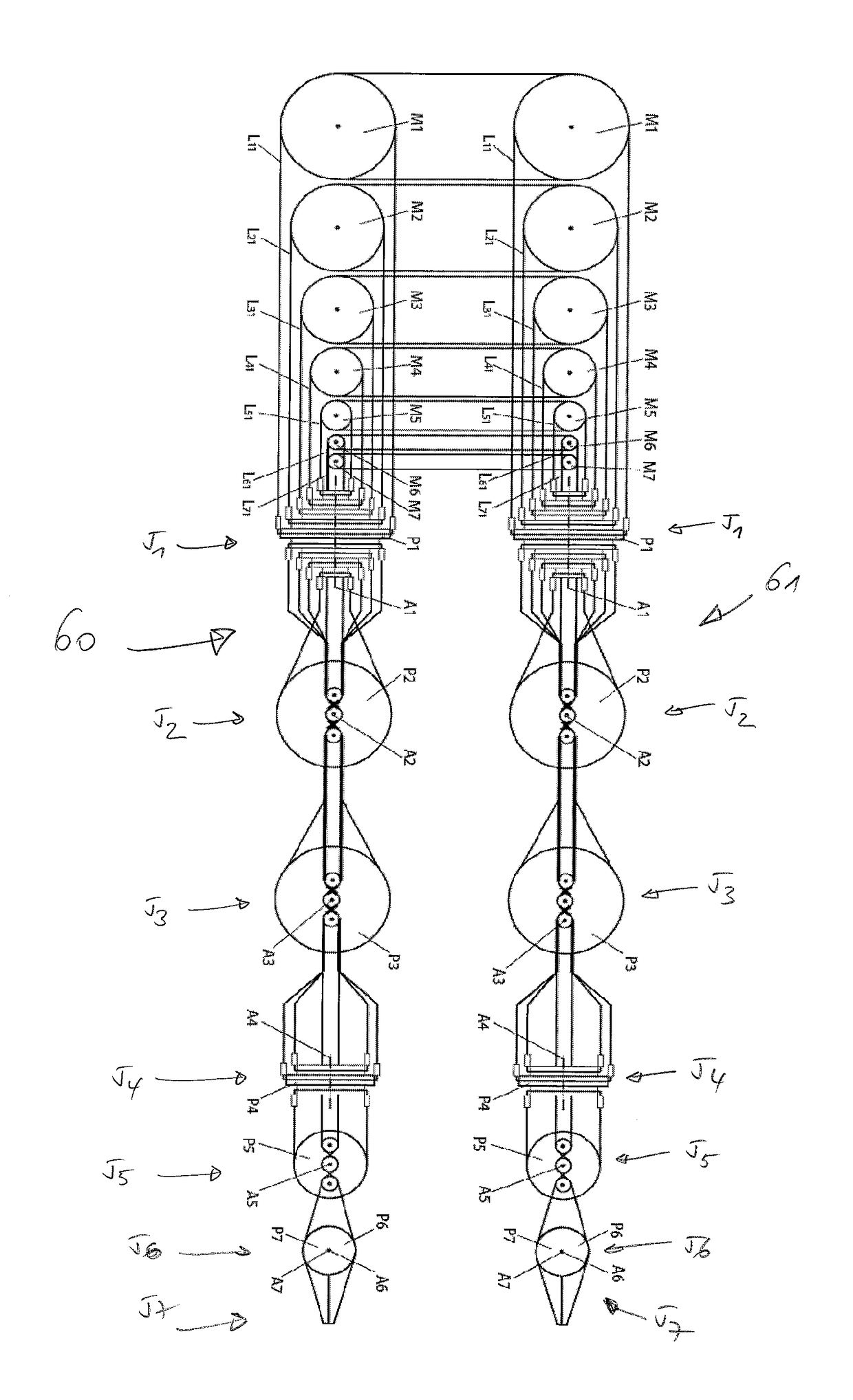
[0102]The present invention will be better understood from the following detailed description and with reference to the drawings which show:

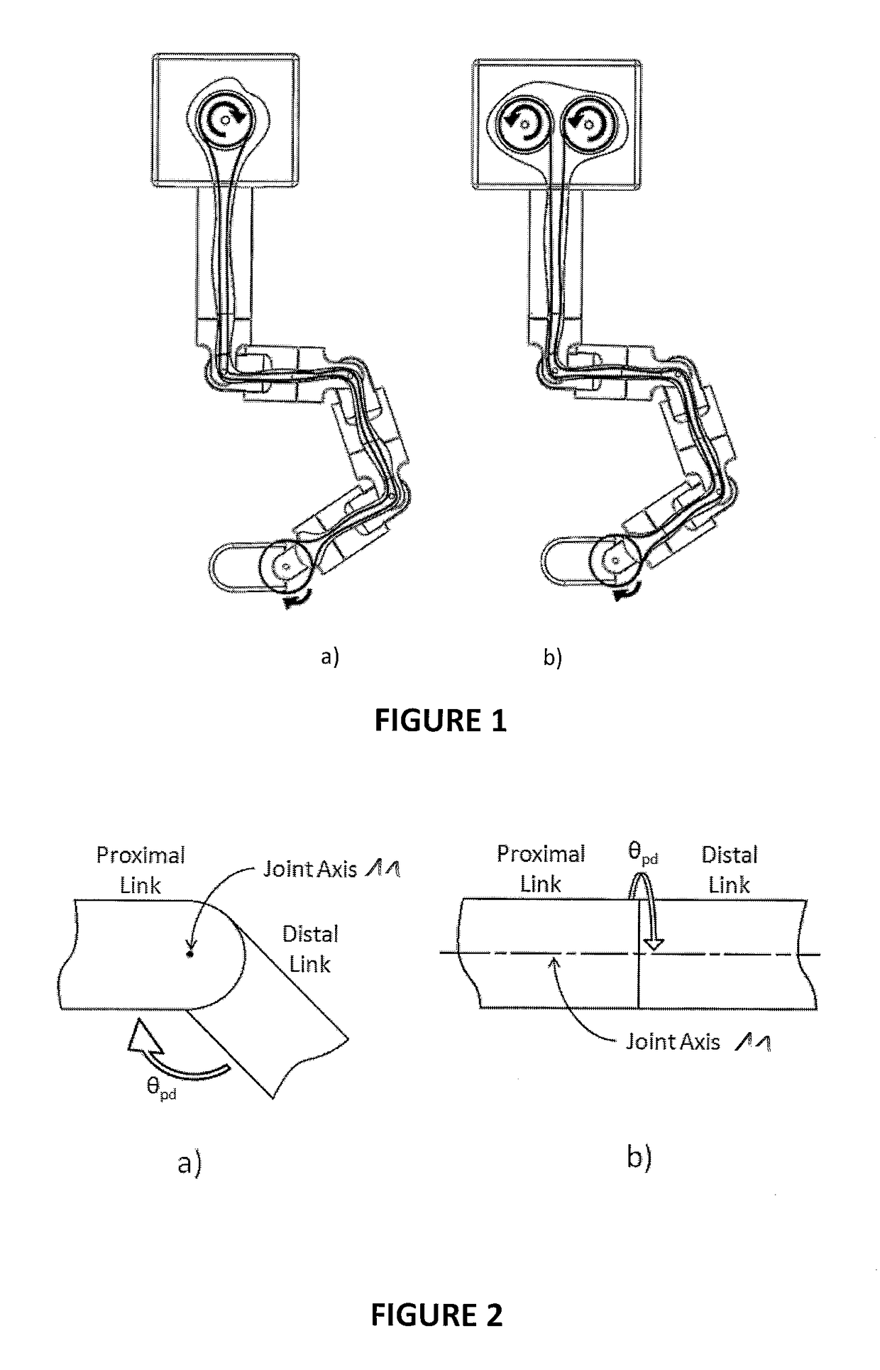
[0103]FIG. 1 illustrates two different architectures for remote actuated cable driven systems, a) One actuated pulley per DOF b) Two actuated pulleys per DOF;

[0104]FIG. 2 illustrates (a) a Pivot Joint and (b) a Co-axial Joint;

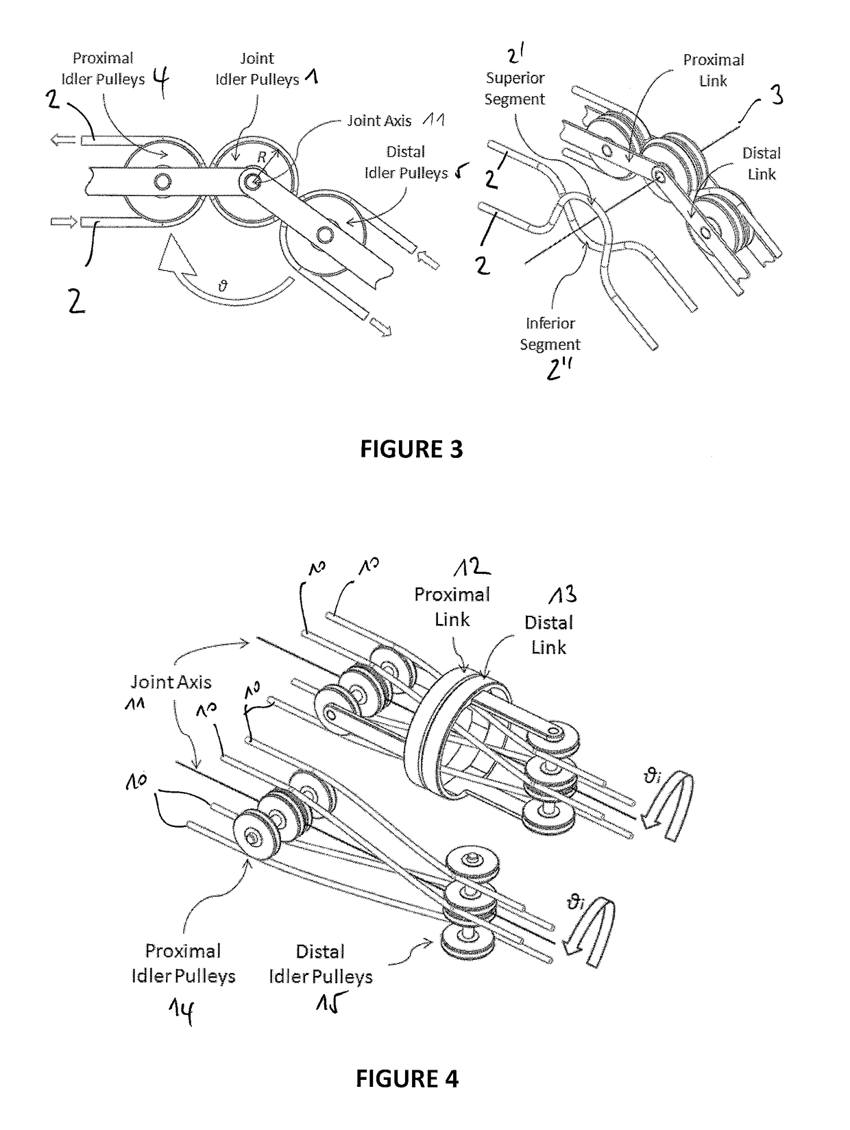
[0105]FIG. 3 illustrates a cable rooting along a Pivot Joint, (a) being a 2D view and (b) being a perspective 3D view;

[0106]FIG. 4 illustrates the problem of the cable routing along a co-axial joint;

[0107]FIG. 5 further illustrates the problem of the cable routing along a co-axial joint;

[0108]FIG. 6 illustrates a Co-axial joint Concept Development;

[0109]FIG. 7 illustrates a Co-axial joint Concept, for a 2-DOF example;

[0110]FIG. 8 illustrates a bead chain turning the idler cylinder;

[0111]FIG. 9 illustrates a use of two ball bearings to mount an idler tube;

[0112]FIG. 10 illustrates a Radial and axial restriction of the joint ...


PUM


Abstract

A novel mechanical system, based on a new cable driven mechanical transmission, able to provide sufficient dexterity, stiffness, speed, precision and payload capacity to actuate multi-DOF micro-manipulators. Besides the possibility of being used in several articulated surgical instruments and robotic systems for surgery or other applications involving remote manipulation, it enables the design of a novel fully mechanical surgical instrument, which offer the advantages of conventional laparoscopy (low cost, tactile feedback, high payload capacity) combined with the advantages of single port surgery (single incision, scarless surgery, navigation through several quadrants of the abdominal cavity) and robotic surgery (greater degrees of freedom, short learning curve, high stiffness, high precision, increased intuition). The unique design of the proposed system provides an intuitive user interface to achieve such enhanced maneuverability, allowing each joint of a teleoperated slave system to be driven by controlling the position of a mechanically connected master unit.

Description

CROSS-REFERENCE TO RELATED APPLICATIONS[0001]This application claims the benefit of European patent application No 10187088.9 and No 10187097.0, both filed on Oct. 11, 2010, the entire disclosure of which is hereby incorporated herein by reference.FIELD OF THE INVENTION[0002]The present invention relates to the field of remotely actuated mechanisms and devices for use in surgical procedures within the abdominal cavity, using reduced incisions in the abdominal wall.BACKGROUND OF THE INVENTION[0003]A major progress in abdominal surgery has occurred during the last decades with the introduction of laparoscopic and minimally invasive techniques. These innovative procedures focused much attention due to their several advantages: smaller abdominal incisions needed, resulting in faster recovery of the patient, improved cosmetics, and shorter stay in the hospital. The safety, efficiency and cost-effectiveness of laparoscopic surgery have subsequently been demonstrated in clinical trials for...

Claims


Application Information

Patent Timeline
Patent Type & Authority Patents(United States)
IPC IPC(8): A61B34/00A61B34/30F16H19/08A61B90/00A61B17/29
CPCA61B34/30A61B34/71F16H19/08Y10T74/18848A61B2017/2906A61B2090/371
Inventor BEIRA, RICARDOCLAVEL, REYMONDBLEULER, HANNES
Owner ECOLE POLYTECHNIQUE FEDERALE DE LAUSANNE (EPFL)
Learn More