
Wall mounted workstation

a workstation and wall mount technology, applied in the field of wall mount workstations, can solve the problems of large mobile units that are typically unused, previous wall mount units are also typically large in design and cumbersome to use, and the caregivers do not provide adequate maneuverability or adjustability, so as to facilitate easy access and interaction, improve the ability to share, and improve the maneuverability and adjustability

Inactive Publication Date: 2007-12-27
STEELCASE INC
View PDF99 Cites 44 Cited by
  • Summary
  • Abstract
  • Description
  • Claims
  • Application Information

AI Technical Summary

Benefits of technology

The present invention provides a workstation support assembly that offers improved maneuverability and adjustability, making it easy to access and interact with computer equipment. The assembly also reduces the amount of floor space required and is compact when in storage. The invention is uncomplicated in design, can be easily assembled and operated, and is particularly well adapted for the proposed use. These technical effects make the invention advantageous for healthcare professionals and patients alike.

Problems solved by technology

However, as floor space within most medical facilities is at a premium, large mobile units typically go unused due to the lack of space and their cumbersome design.
Further, previous wall-mounted units are also typically large in design and cumbersome to use.
Moreover, these units do not provide adequate maneuverability or adjustability to the caregiver to allow easy access to the information, and / or to allow the caregiver to easily share information and images with other physicians attending to the patient, or with the patient themselves.

Method used


Image

  • Wall mounted workstation
  • Wall mounted workstation
  • Wall mounted workstation

Examples


Embodiment Construction

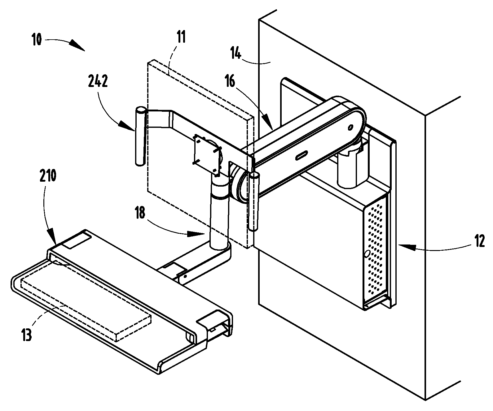
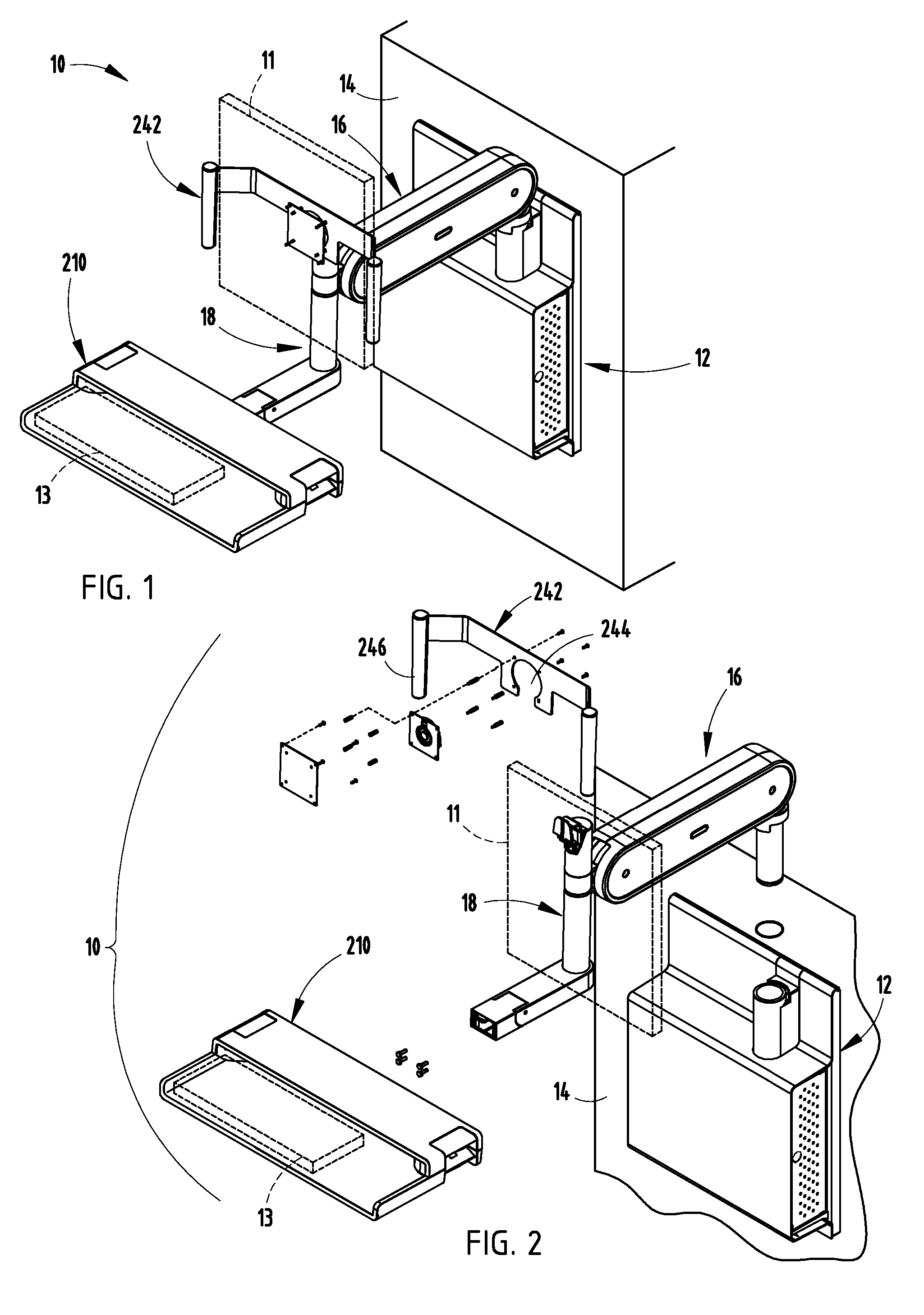
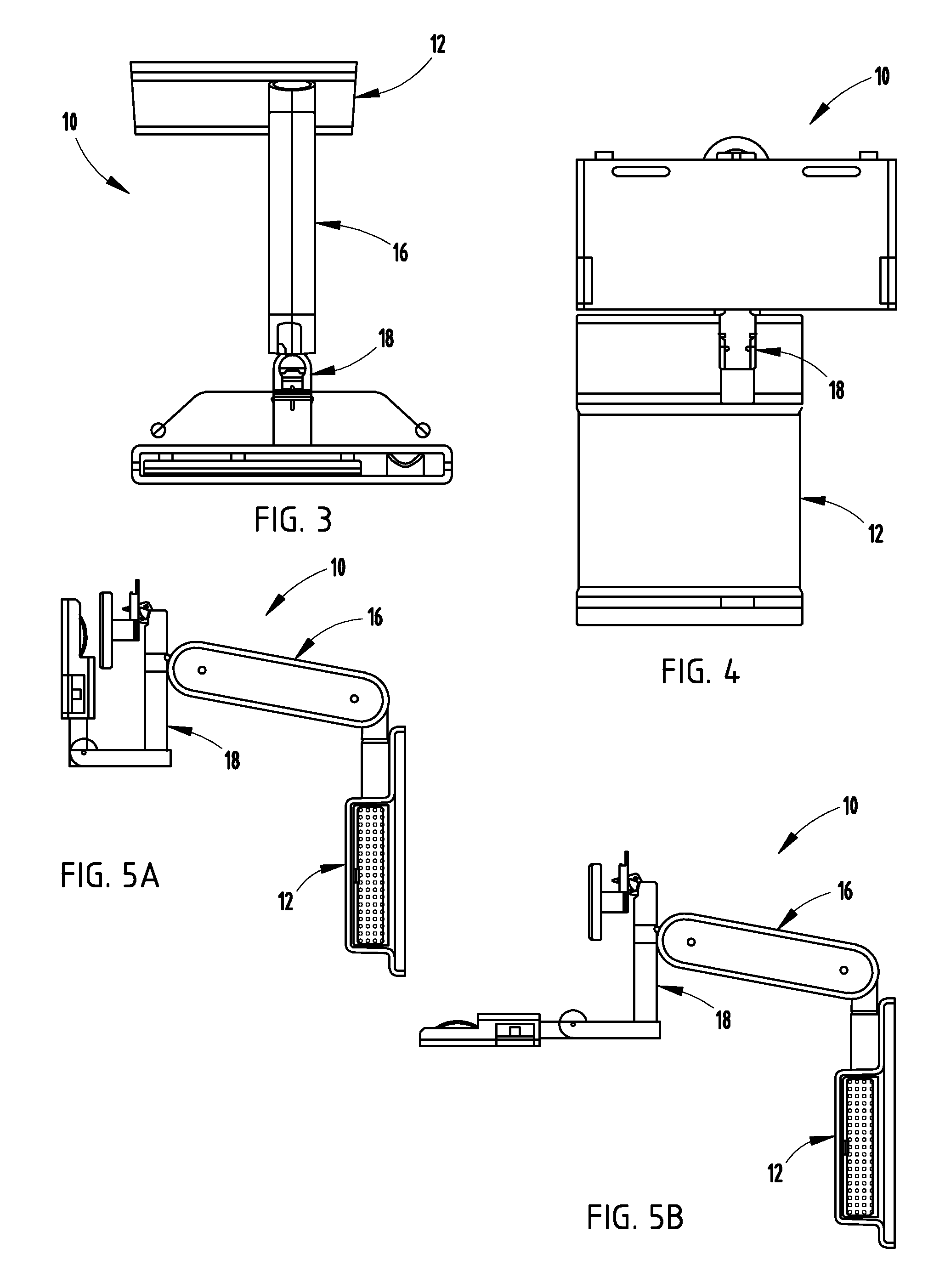
[0047] For purposes of description herein, the terms “upper,”“lower,”“right,”“left,”“rear,”“front,”“vertical,”“horizontal,” and derivatives thereof shall relate to the invention as oriented in FIG. 1. However, it is to be understood that the invention may assume various alternative orientations and step sequences, except where expressly specified to the contrary. It is also to be understood that the specific devices and processes illustrated in the attached drawings, and described in the following specification are exemplary embodiments of the inventive concepts defined in the appended claims. Hence, specific dimensions and other physical characteristics relating to the embodiments disclosed herein are not to be considered as limiting, unless the claims expressly state otherwise.

[0048] The reference numeral 10 (FIGS. 1 and 2) generally designates a workstation assembly embodying the present invention, that is adapted for use within medical facilities, and particularly for use withi...


PUM


Abstract

A workstation support assembly comprises a support assembly, a post assembly rotationally supported by the support assembly and including a post member, a computer monitor support assembly operably coupled for rotation with a first end of the post member, and a keyboard support assembly operably coupled for rotation with a second end of the post member, wherein rotation of the keyboard support assembly forces rotation of the post member and the monitor support assembly, and wherein rotation of the monitor support assembly does not force the rotation of the keyboard support assembly. Other aspects of the workstation comprise a four-bar linkage support arm that includes a cable management member extending therethrough for receiving and guiding wires within an interior passage of the support arm, a lockable pneumatic cylinder located within the support arm and adapted to lock the support arm at a given vertical position, a housing assembly that spans the distance between vertical studs within commercial wall structures, thereby eliminating the requirement for additional mounting structures, and a keyboard support assembly that includes a cam assembly for locking an adjustable keyboard in a storage position, and a storage compartment for slidably receiving a computer mouse therein when the keyboard support is in the storage position.

Description

CROSS-REFERENCE TO RELATED APPLICATION [0001] This application claims the benefit of U.S. Provisional Application No. 60 / 812,793, filed Jun. 12, 2006, entitled WALL MOUNTED WORKSTATION, which is hereby incorporated herein by reference in its entirety.BACKGROUND OF THE INVENTION [0002] The present invention relates to a workstation assembly, and in particular to a wall-mounted workstation assembly that operably supports a computer monitor and a computer keyboard and that provides both coupled and individual manipulation and maneuvering thereof. [0003] Workstation assemblies adapted to support computer monitors and / or computer keyboards encompass a wide variety of designs that are adapted to be used in various work settings. Many of these designs are specifically adapted to be used within a particular work environment. One such work environment is that dictated by the medical field. Specifically, numerous advancements in electronic patient information allow medical practitioners easy ...

Claims


Application Information

Patent Timeline
Patent Type & Authority Applications(United States)
IPC IPC(8): F16M11/00
CPCF16M11/04F16M11/10F16M11/2014F16M2200/065F16M13/02F16M2200/044F16M2200/063F16M11/24Y10S248/921
Inventor PETERSON, ERIK R.TATMAN, DAN R.ADAMS, MATTHEW R.HENNINGSBAARD, AARON A.INOUYE, MATTHEW D.KAPLAN, JOHATHAN I.LUKIC, BRANKOSHARP, PHILLIP N.SIBERSCHATZ, PAUL J.SENDIL, ALTAY J.
Owner STEELCASE INC
Learn More