Gate apparatus for tufting loop and cut pile stitches

a technology of tufting loops and tufting stitches, which is applied in the field of tufting loops and cut pile stitches, and can solve the problems of waste of carpet, limiting the speed with which the gate can return to the open position, and not allowing effective control of the height of stitches

Inactive Publication Date: 2007-05-29
TUFTCO
View PDF11 Cites 44 Cited by
  • Summary
  • Abstract
  • Description
  • Claims
  • Application Information

AI Technical Summary

Benefits of technology

[0006]Therefore, it is a primary object of the invention to provide an improved sliding gate structure for use in tufting both loop pile and cut pile stitches from yarns seized by the same looper.
[0008]It is yet another object of the invention to provide discrete pneumatic cylinders and biasing means so that a defective element may be replaced without the need for replacing an entire module or block of components.
[0009]It is still a further object of the invention to provide an array of pneumatic cylinders and corresponding activated sliding gates in a compact form so as to be effectively employed with narrow gauge needle configurations according to the present invention.

Problems solved by technology

In some instances, the structures utilized for this purpose did not allow effective control of the height of stitches and, for instance, the cut pile stitches might always be of greater height than the loop pile stitches.
In turn, this limits the speed with which the gate can return to the open position after pressure to its corresponding pneumatic cylinder is stopped.
Furthermore, the internal biasing elements are not visible to inspection and if rust beings to form due to moisture in the cylinder, for instance, there will be no way to detect the problem until performance degrades to the point where defective carpet patterns are produced, with resulting waste carpet and the need to replace an entire cylinder block rather than merely a spring or biasing element.

Method used


Image

  • Gate apparatus for tufting loop and cut pile stitches
  • Gate apparatus for tufting loop and cut pile stitches
  • Gate apparatus for tufting loop and cut pile stitches

Examples


Embodiment Construction

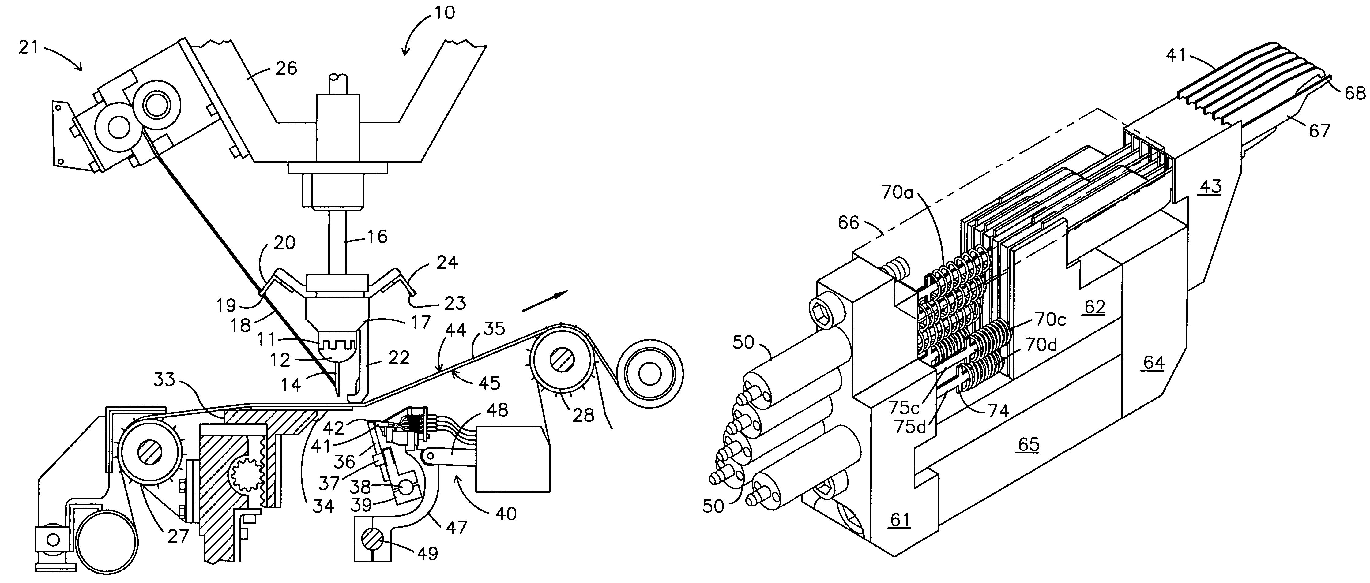
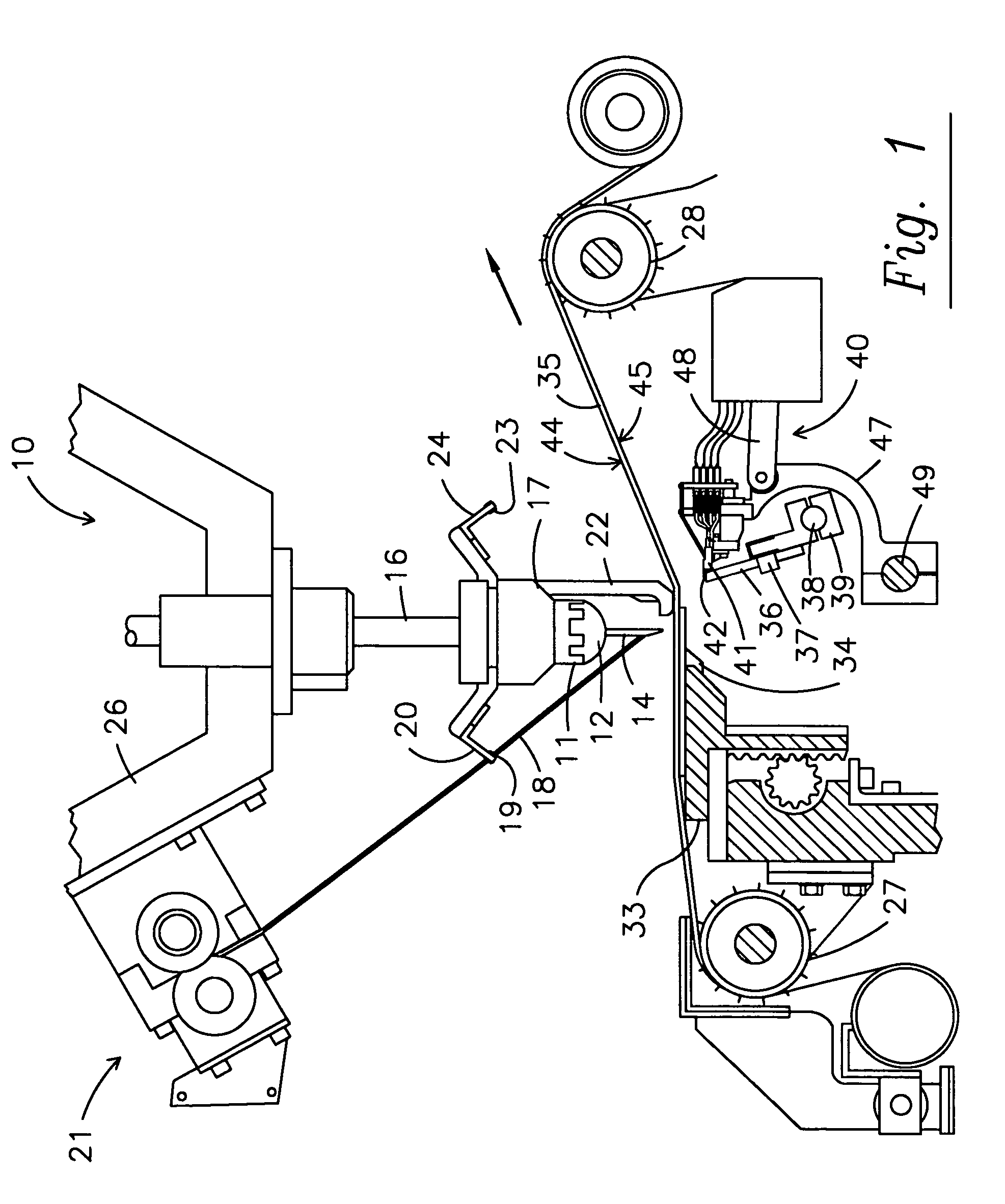
[0022]FIG. 1 discloses a tufting machine 10 including transversely supported needle bar 12 which in turns supports a row of transversely spaced needles 14. The needle bar carrier 11 is connected to push rod 16 adapted to be vertically reciprocated by a conventional needle drive mechanism, not shown. Front yarns 18 are supplied to the needles 14 through apertures 19 in the front yarn guide plate 20 from a source of yarn supply, not shown, such as yarn feed rolls, creels, or other known yarn supply means. Preferably the front yarns pass through a yarn feed pattern control mechanism 21 adapted to feed the appropriate length of individual yarns 18 to corresponding needles 14 in accordance with a pre-determined pattern. Any one of several pattern control mechanisms may be incorporated in the mechanism 21 such as those disclosed in U.S. Pat. Nos. 6,244,203 and 6,283,053, or earlier mechanisms, and typically attach to the head 26 of tufting machine 10.

[0023]When needed, rear yarns may be c...


PUM


Abstract

A gated looper apparatus has an array of individually mounted pressurizable air cylinders with piston rods acting against biased slider bars in communication with looper gates. Baising elements are mounted external of pneumatic cylinders about slider bars with protective ferules to provide greater responsiveness and ease of maintenance.

Description

RELATED U.S. APPLICATION DATA[0001]This application claims the benefit of U.S. Provisional Application No. 60 / 649,505 filed Feb. 3, 2005 which is incorporated herein by reference.FIELD OF THE INVENTION[0002]The present invention relates to the manufacture of tufted fabrics, and particularly to an improved gate apparatus to allow a looper to tuft either loop pile or cut pile stitches.BACKGROUND OF THE INVENTION[0003]In the field of tufting, there have been a variety of efforts made to enable both cut pile and loop pile tufts or bights of yarn to be placed in the same row of stitches. In some instances, the structures utilized for this purpose did not allow effective control of the height of stitches and, for instance, the cut pile stitches might always be of greater height than the loop pile stitches. The use of pivoting gate structures on the loopers was proposed in Jolley, U.S. Pat. No. 4,134,347 and Crumbliss, U.S. Pat. No. 4,353,317.[0004]Later sliding gate structures were propos...

Claims


Application Information

Patent Timeline
Patent Type & Authority Patents(United States)
IPC IPC(8): D05C15/22D05B57/00
CPCD05C15/22D05C15/36
Inventor KILGORE, MICHAEL
Owner TUFTCO
Why Eureka
Try Eureka