Design of robotic gait rehabilitation by optimal motion of the hip

a robotic and hip technology, applied in the field of robotic gait rehabilitation, can solve the problems of limited clinical access to bws training, inability to optimally adjust the fixed trajectory of patients, and common impairment of walking ability after such neurologic injuries

Inactive Publication Date: 2007-01-18
REINKENSMEYER DAVID J +4
View PDF12 Cites 46 Cited by
  • Summary
  • Abstract
  • Description
  • Claims
  • Application Information

AI Technical Summary

Problems solved by technology

Impairment in walking ability after such neurologic injuries is common.
Clinical access to BWS training is currently limited because the training is labor intensive.
Such a fixed trajectory cannot be optimal for every patient.
One difficulty in automating BWS training is that the required patterns of forces at the hips and legs are unknown.
However, therapists are relatively limited in the forces that they can apply compared to robots, and there is no guarantee that any given therapist has selected an optimal solution.

Method used


Image

  • Design of robotic gait rehabilitation by optimal motion of the hip
  • Design of robotic gait rehabilitation by optimal motion of the hip
  • Design of robotic gait rehabilitation by optimal motion of the hip

Examples


example 1

[0066] This example shows the robotic device in motion capture mode.

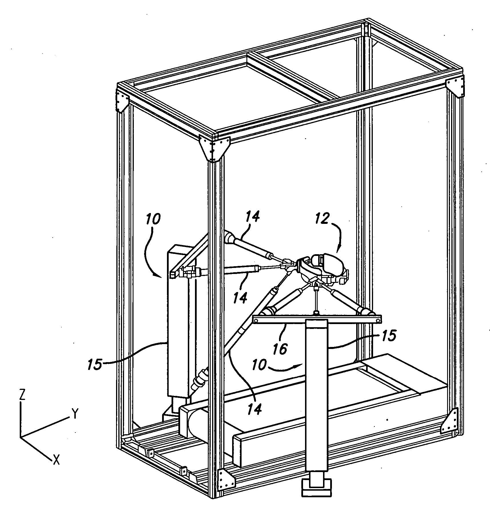
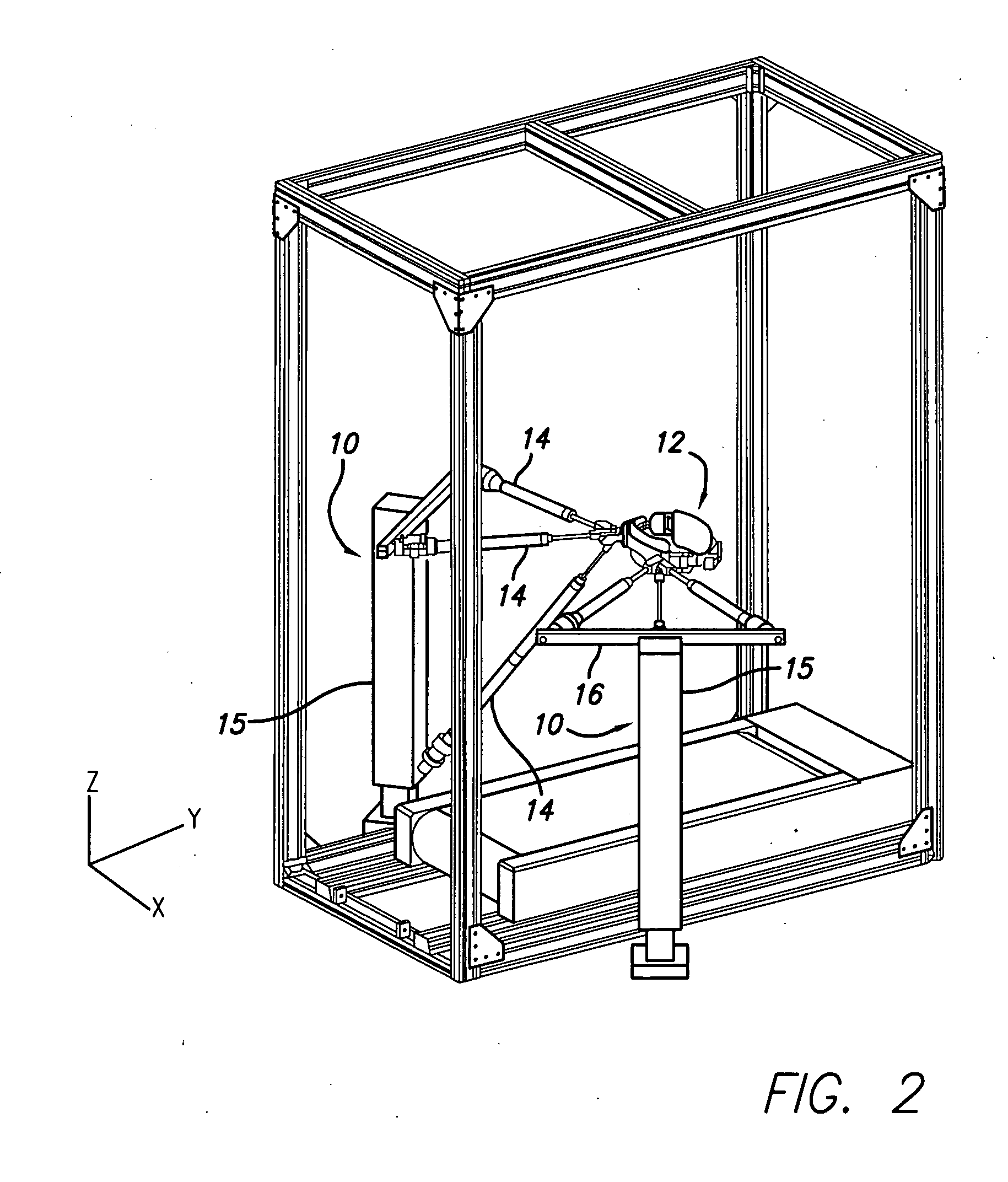
[0067] Each robot of the device uses three 1.5″ diameter pneumatic cylinders, each cylinder with a 12″ stroke. The device can generate about 350 lbs of force in the X-direction, 200 lbs of force in the Y-direction, and 140 lbs of force in the Z-direction, with reference to the X, Y and Z axes of FIG. 2, at a 100 PSI supply pressure. The positions of the cylinder rods are measured by an analog voltage signal from potentiometers that are integral within the cylinders. Pressures on each side of each cylinder are measured using low-cost pressure sensors. The system is controlled using Matlab xPC target.

[0068] The cylinder lengths can accommodate hip movement within an approximately 15-centimeter sphere. The resulting workspace allows for both normative and moderately exaggerated hip movements should they be necessary. FIG. 6A shows the workspace of the device in the horizontal (X-Y) plane, where the X, Y and Z axes ar...

example 2

[0072] This example shows the use of dynamic motion optimization applied to a fully actuated model. This model simulates normal human control of stepping.

[0073] Motion capture data was obtained from an unimpaired human subject with a height of 1.95 m and a weight of 75 kg. The sampling rate of motion capture was 60 Hz. The treadmill speed was selected to be 1.25 m / sec to approximate a speed commonly used in step training with BWS training. FIGS. 9A-C show one representative step with a duration of 0.5 sec that was chosen for comparison with the optimization results. The positions of the external markers were converted to link lengths and joint angles based on forward kinematics. The X, Y and Z axes are oriented as shown in FIG. 5. FIG. 9A shows the subject's gait along the X-Z plane. FIG. 9B shows a side view of the gait along the X-Y plane, where a solid line 90 represents the subject's swing leg during the step cycle and a dashed line 92 represents the configuration of the stance...

example 3

[0080] This example shows the use of dynamic motion optimization applied to an under-actuated model, which simulates a paralyzed subject.

[0081] For this analysis, the swing hip, knee and ankle joints were made passive. A total of 16 parameters (8 for each actuated joint) were used in the optimization. The optimization took approximately 3.5 hours to complete. The results are shown in FIGS. 13-15.

[0082] Referring to FIGS. 13A-C, FIG. 13A shows the gait in the X-Z plane, with a solid line 160 representing the optimized gait and a dashed line 162 representing the actual human data. FIG. 13B shows the gait in the Y-X plane, with a solid line 164 representing the optimized gait and a dashed line 166 representing the actual human data. FIG. 13C shows the gait in the Y-Z plane with the solid line 168 representing the optimized gait and the dashed line 170 representing the actual human data.

[0083] Referring to FIGS. 14A-G which show the joint angles in degrees during the step cycle, FIG....


PUM


Abstract

A method and a robotic device for locomotion training. The method involves shifting a subject's pelvis without directly contacting the subject's leg, thereby causing the subject's legs to move along a moveable surface. The device comprises two backdriveable robots, each having three pneumatic cylinders that connect to each other at their rod ends for attachment to the subject's torso. Also provided is a method of determining a locomotion training strategy for a pelvic-shifting robot by incorporating dynamic motion optimization.

Description

CROSS-REFERENCE TO RELATED APPLICATIONS [0001] This application claims the benefit of provisional application No. 60 / 382,137 filed on May 20, 2002.STATEMENT REGARDING FEDERALLY SPONSORED RESEARCH OR DEVELOPMENT [0002] This invention was made with Government Support under Grant No. ATP 00-00-4906, awarded by the National Institute of Standards and Technology. The Government has certain rights in this invention.BACKGROUND [0003] 1. Field of Invention [0004] This invention relates generally to a method and device for controlling the stepping motion of a subject undergoing locomotion rehabilitation. [0005] 2. Related Art [0006] In the U.S. alone, over 700,000 people experience a stroke each year, and over 10,000 people experience a traumatic spinal cord injury. Impairment in walking ability after such neurologic injuries is common. Recently, a new approach to locomotion rehabilitation called body weight supported (herein referred to as “BWS”) training has shown promise in improving loco...

Claims


Application Information

Patent Timeline
Patent Type & Authority Applications(United States)
IPC IPC(8): A61H3/00
CPCA61H3/008A63B21/00181A63B69/0064A61H1/0262A63B22/0235A61H2201/0192A61H2201/1238A61H2201/163A61H2201/164A61H2201/165A61H2201/1664A61H2201/1666A61H2201/5061A61H2201/5071A61H2003/007
Inventor REINKENSMEYER, DAVID J.HARKEMA, SUSAN J.EDGERTON, V. REGGIEBOBROW, JAMESWANG, CHIA YU
Owner REINKENSMEYER DAVID J
Why Eureka
Try Eureka