Lighting device

A technology for lighting devices and transparent materials, applied in lighting devices, display devices, illuminated signs, etc., can solve the problems of difficult brightness, poor light transmittance of light guide plates, low light transmittance of lighting devices, etc., to achieve full transparency transient effect

Inactive Publication Date: 2012-05-30
HAYAMIZU ELECTRIC INDS +1
View PDF7 Cites 6 Cited by
  • Summary
  • Abstract
  • Description
  • Claims
  • Application Information

AI Technical Summary

Problems solved by technology

In the lighting device disclosed in Patent Document 1, although a substrate with high transparency is used, a light-diffusing material using a transparent or white pigment is mixed in the substrate material, making it difficult to maintain constant brightness over the entire surface of the light guide plate. In addition, there is a problem that the light transmittance of the lighting device during lighting is low
[0010] In addition, according to Patent Document 2, since a reflection plate is provided on one surface of the light guide plate, there is a problem that the light transmittance of the lighting device is low.
[0011] In addition, in Patent Document 3, since a pattern filter is provided on the light emitting layer, there is a problem that the light transmission of the light guide plate is poor.

Method used


Image

  • Lighting device
  • Lighting device
  • Lighting device

Examples


Embodiment Construction

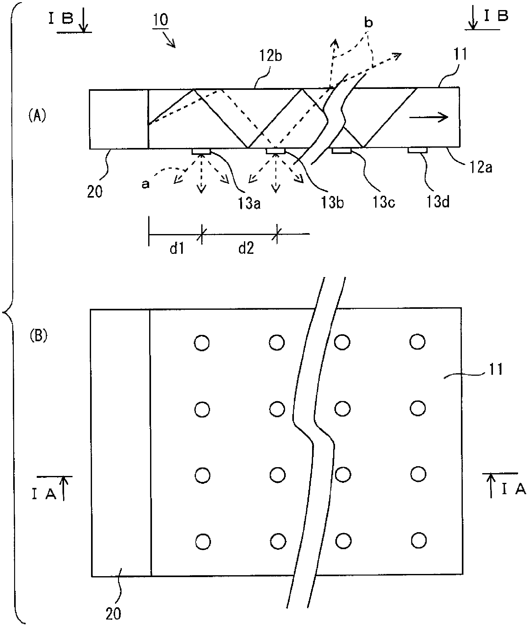
[0026] Hereinafter, an embodiment of the present invention will be described with reference to the drawings. figure 1 It is a figure which shows the illuminating device 10 which concerns on one Embodiment of this invention. figure 1 (A) is a sectional view of the lighting device 10 (in figure 1 (B) in the figure indicated by the arrow IA-IA), figure 1 (B) is figure 1 Arrow view indicated by arrows IB-IB in (A).

[0027] refer to figure 1 , The lighting device 10 includes: a light guide plate 11, which is formed of a transparent material such as rectangular glass or acrylic plate with one side 12a and the opposite side 12b; a dot pattern (dot-like screen printing pattern) 13a...13d, which are arranged on one side 12a of the light guide plate 11 and are printed with special ink; and LED light sources 20, which are arranged on the end surface connecting the one side of the light guide plate 11 and the opposite side and the light guide plate 11 relative positions.

[0028] H...


PUM


Abstract

A lighting device (10) includes a light guide plate (11) consisting of a transparent material and having a pair of opposed surfaces and end surfaces for interconnecting the pair of opposed surfaces (12a, 12b); a dot-patterned silk printing pattern (13) provided on the surface (12a) of the light guide plate (11), formed using special ink, and diffusing light; and an LED light source (20) provided to a position facing an end surface of the light guide plate (11). The surface (12a) of the light guide plate (11), on which surface the silk printing pattern (13) is formed, functions intact as a light emitting surface.

Description

technical field [0001] The invention relates to a lighting device, in particular to a transparent lighting device. Background technique [0002] Existing lighting devices are described in, for example, Japanese Patent Laid-Open No. 2007-141735 (hereinafter referred to as "Patent Document 1"), Japanese Patent Laid-Open No. 2007-80531 (hereinafter referred to as "Cited Document 2"), Japanese Patent Laid-Open Publication Hei It is disclosed in Publication No. 08-160892 (hereinafter referred to as "Citation Document 3"). [0003] According to Patent Document 1, there is disclosed a double-sided light-emitting panel including a light guide plate having a plurality of plasma lamps on end faces, transparent acrylic plates provided on both sides of the light guide plate, and advertising media provided on the acrylic plate. Here, as a transparent substrate used as a light guide plate, a substrate with high transparency such as polymethyl methacrylate, (meth)acrylate copolymer, polyc...

Claims


Application Information

Patent Timeline
Patent Type & Authority Applications(China)
IPC IPC(8): F21S2/00F21Y101/02
CPCG02B6/0043G02B6/006F21Y2105/00G09F13/18F21Y2101/02F21Y2115/10F21K2/00
Inventor 冲孝二
Owner HAYAMIZU ELECTRIC INDS
Why Eureka
Try Eureka