Lens barrel, imaging device and mobile terminal device

A technology of lens barrel and camera device, which is applied in installation, photography, optics, etc., and can solve problems such as lens changes, image plane curvature, and camera lens resolution reduction.

Inactive Publication Date: 2012-05-30
PANASONIC CORP
View PDF6 Cites 16 Cited by
  • Summary
  • Abstract
  • Description
  • Claims
  • Application Information

AI Technical Summary

Problems solved by technology

[0004] However, in the imaging device using the lens barrel disclosed in Patent Document 1, the gap between lenses, which tends to affect curvature of field, fluctuates due to thickness variations caused by individual differences in spacers and lenses.
As a result, curvature of field occurs and the resolution of the imaging lens decreases.

Method used


Image

  • Lens barrel, imaging device and mobile terminal device
  • Lens barrel, imaging device and mobile terminal device
  • Lens barrel, imaging device and mobile terminal device

Examples


Embodiment approach

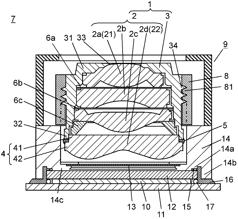
[0021] figure 1 It is a side sectional view showing the lens barrel 1 and the imaging device 7 according to the embodiment of the present invention.

[0022] Such as figure 1 As shown, the lens barrel 1 is composed of at least an imaging lens 2, a lens holder 3, and a resin spacer 6c. The imaging lens 2 is composed of a plurality of three or more lenses. In addition, in this embodiment, the example which consists of 4 lenses 2a-2d is demonstrated. The imaging lens 2 is inserted into the lens holder 3 to accommodate the imaging lens 2 . The resin spacer 6 c has elasticity in the optical axis direction and is provided between lenses (in this embodiment, between the lenses 2 c and 2 d ) that tend to affect field curvature among the imaging lenses 2 . Then, the lens barrel 1 is configured such that lenses that are likely to affect curvature of field are pressed, and the resin spacer 6 c is positioned and fixed with, for example, an adhesive or the like while the resin spacer 6...


PUM


Abstract

A lens barrel is provided with a lens holder, and an imaging lens composed of a plurality of three or more lenses inserted and fitted into the lens holder. The lens barrel is configured in such a manner that resin spacers having elasticity in the optical axis direction are disposed between the lenses that affect the curvature of field, and a pressing force is applied between the lenses that affect the curvature of field, thereby deforming the resin spacers so as to be fixed in place. Thus, a pressing force is applied between the lenses, which easily affect the curvature of field, thereby elastically deforming the resin spacers in the optical axis direction, enabling the space between the lenses to be adjusted. As a result, the curvature of field can be corrected, and a reduction in resolving power can be prevented.

Description

technical field [0001] The present invention relates to configurations of a lens barrel, an imaging device, a mobile terminal device, and the like. Background technique [0002] In recent years, in lens barrels mounted on mobile terminal devices such as camera phones and information mobile terminals, downsizing of lens barrels and the like has been demanded in order to reduce the mounting space. In addition, due to the increase in the size of the imaging element and the high resolution of the pixels, a high-resolution imaging lens is required. [0003] The existing lens barrel has a lens unit, and the lens unit is equipped with the following: a plurality of lenses inserted in the lens frame; gaskets arranged between each lens; A pressing part that presses the lens on one end side to the other end side; a lens pressing member that presses the lens on the other end side in the optical axis direction to the one end side in the optical axis direction, and fixes each lens and sp...

Claims


Application Information

Patent Timeline
Patent Type & Authority Applications(China)
IPC IPC(8): G02B7/02
CPCG02B7/022G02B13/004G02B13/001G03B33/00
Inventor 吉村宪久
Owner PANASONIC CORP
Why Eureka
Try Eureka