LPI ejector

An injector and injection pipe technology, which is applied to fuel injection devices, machines/engines, mechanical equipment, etc., can solve problems such as injection defects, poor quality of exhaust gas, and uneven fuel supply.

Inactive Publication Date: 2012-06-06
HYUNDAI MOTOR CO LTD +1
View PDF6 Cites 0 Cited by
  • Summary
  • Abstract
  • Description
  • Claims
  • Application Information

AI Technical Summary

Problems solved by technology

A portion of the liquid fuel passes through this void and evaporates producing tar, which solidifies and closes the fuel injection hole, causing it to exhibit injection defects
Also, the fuel supply does not go smoothly, resulting in poor exhaust gas quality or engine shutdown

Method used


Image

  • LPI ejector
  • LPI ejector
  • LPI ejector

Examples


Embodiment Construction

[0025] Hereinafter, an LPI injector according to an exemplary embodiment of the present invention will be described in detail with reference to the accompanying drawings. However, the present invention is not limited to the exemplary embodiments to be disclosed hereinafter, and the present invention can be implemented in various forms. It will be appreciated by those skilled in the art that changes may be made in these embodiments without departing from the principles and spirit of the general inventive concept, the scope of which is defined in the appended claims and their equivalents.

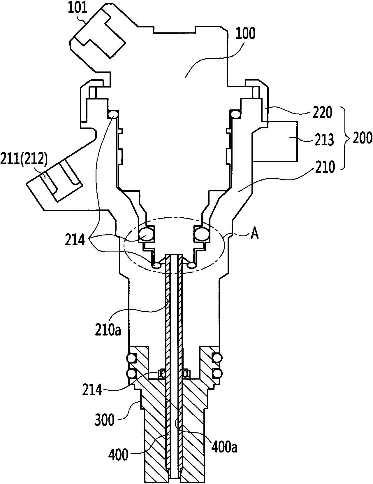
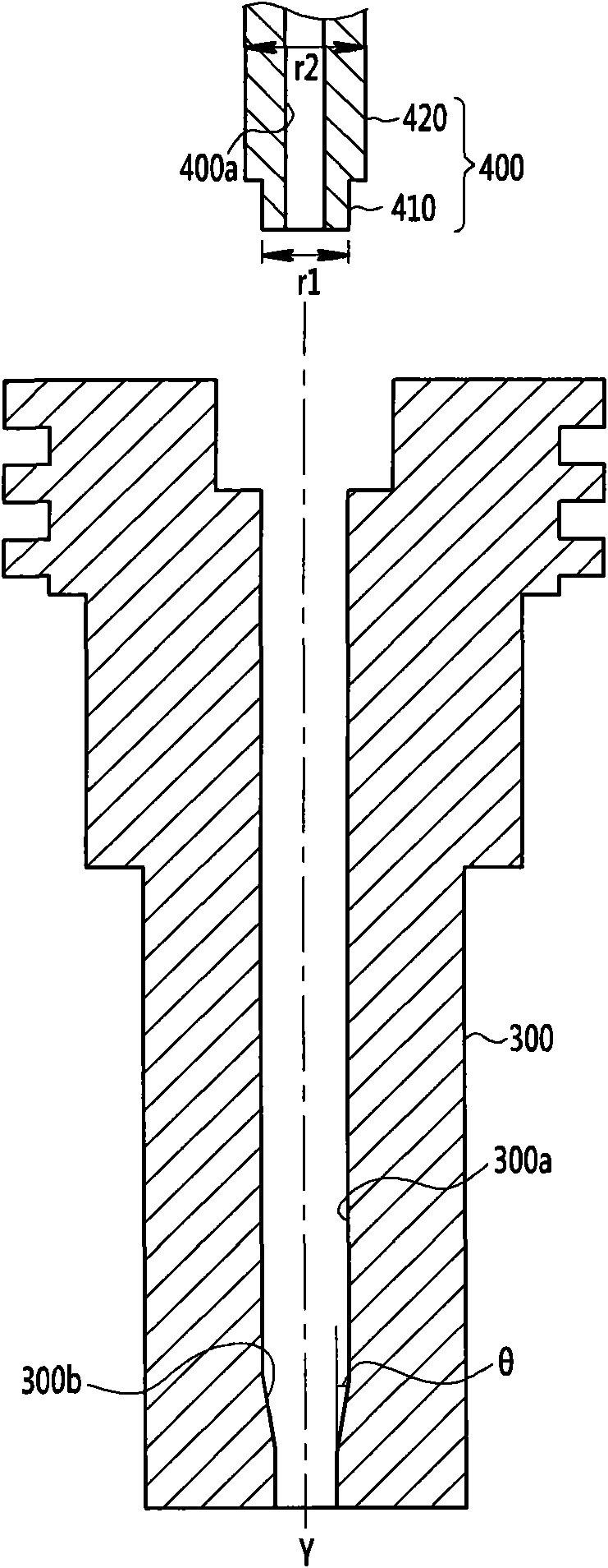
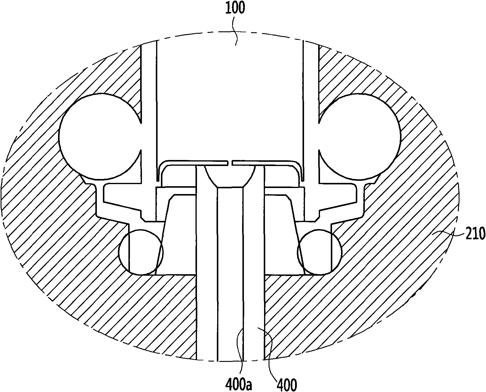
[0026] figure 1 is a cross-sectional view of an LPI injector according to an exemplary embodiment of the present invention, figure 2 yes figure 1 An exploded view of the jet tube and icing tip, image 3 yes figure 1 A magnified view of part A.

[0027] Such as Figure 1 to Figure 3 As shown, the LPI injector according to the exemplary embodiment of the present invention includes: an in...


PUM


Abstract

The invention discloses an LPI ejector. According to the embodiment provided in the invention, the LPI ejector comprises an ejector part, a housing covering an outer periphery of the ejector part, a freezing tip, which is combined with a lower part of the housing and is provided with a tip penetrating part, and an ejection pipe, which is communicated with a lower end part of the ejector part, is penetrated through the tip penetrating part. And a cone-shaped part can be formed on the lower end part of the tip penetrating part.

Description

[0001] Cross References to Related Applications [0002] This application claims priority and benefit from Korean Patent Application No. 10-2010-0123555 filed in the Korean Intellectual Property Office on December 6, 2010, the entire contents of which are hereby incorporated by reference. technical field [0003] The present invention relates to an LPI injector. More particularly, the present invention relates to an LPI injector that prevents LPG fuel from remaining between an injection portion and an injection pipe. Background technique [0004] In general, an LPI (Liquefied Petroleum Gas Injection) engine includes a fuel pump arranged in a fuel tank, in which LPG fuel is liquefied by its high pressure of 5 to 15 bar, and injectors inject the liquefied fuel into each cylinder of the engine so that the engine Running, this is a new technology (Mono fuel method). [0005] Since the LPI engine injects liquid fuel into the cylinder, components such as the carburetor and mixer...

Claims


Application Information

Patent Timeline
Patent Type & Authority Applications(China)
IPC IPC(8): F02M61/18F02M21/02
CPCY02T10/32Y02T10/123Y02T10/12Y02T10/30F02M21/0248F02M53/04F02M61/168F02M61/18
Inventor 宋珍五
Owner HYUNDAI MOTOR CO LTD
Why Eureka
Try Eureka