
Clutch, steering engine and robot

A technology of clutches and clutch teeth, which is applied in manipulators, program-controlled manipulators, manufacturing tools, etc., can solve problems such as the difficulty of clutch teeth jumping, and achieve the effects of strong stability, reduced vibration, and not easy to break and damage

Active Publication Date: 2020-04-17
UBTECH ROBOTICS CORP LTD
View PDF6 Cites 3 Cited by
  • Summary
  • Abstract
  • Description
  • Claims
  • Application Information

AI Technical Summary

Problems solved by technology

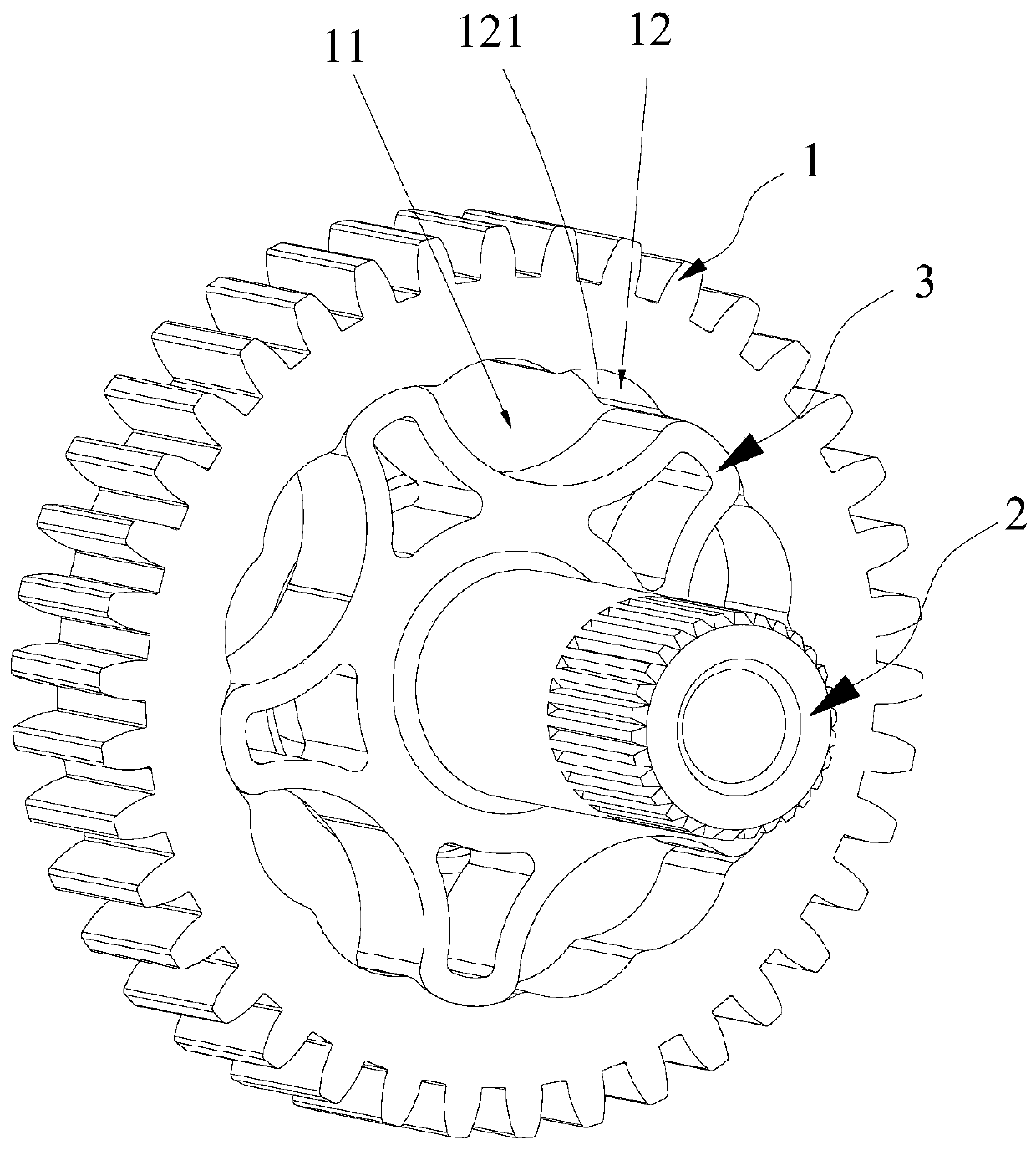
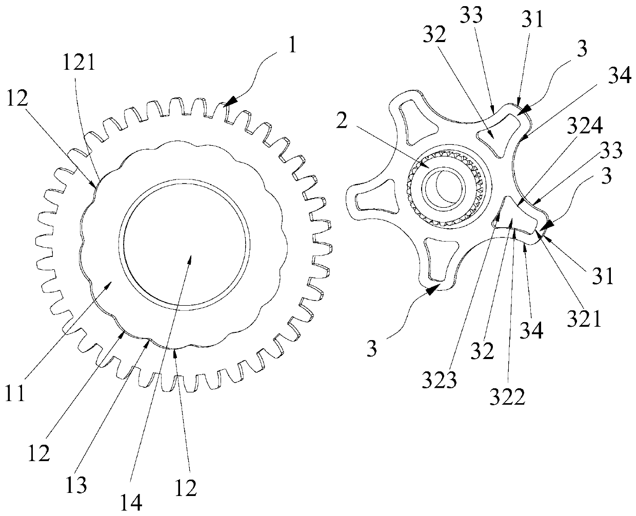
[0003] An object of the present application is to provide a clutch, which aims to solve the problem in the prior art that the clutch teeth are not easy to jump

Method used


Image

  • Clutch, steering engine and robot
  • Clutch, steering engine and robot
  • Clutch, steering engine and robot

Examples


Embodiment Construction

[0035] In order to make the purpose, technical solution and advantages of the present application clearer, the present application will be further described in detail below in conjunction with the accompanying drawings and embodiments. It should be understood that the specific embodiments described here are only used to explain the present application, and are not intended to limit the present application.

[0036] It should be noted that when an element is referred to as being “fixed” or “disposed on” another element, it may be directly on the other element or be indirectly on the other element. When an element is referred to as being "connected to" another element, it can be directly connected to the other element or indirectly connected to the other element.

[0037] It is to be understood that the terms "length", "width", "top", "bottom", "front", "rear", "left", "right", "vertical", "horizontal", "top" , "bottom", "inner", "outer" and other indicated orientations or posi...


PUM


Abstract

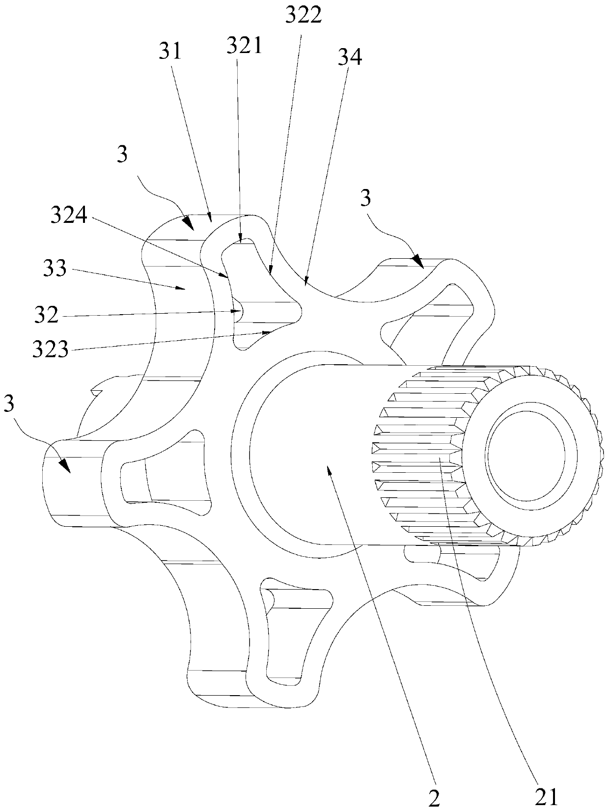
The invention discloses a clutch. The clutch comprises an output gear, a rotating shaft and at least one clutch tooth arranged on the rotating shaft, wherein the output gear is provided with a containing groove; the inner side wall, positioned in the containing groove, of the output gear is provided with a plurality of inner tooth grooves matched with the clutch teeth; the ends, away from the rotating shaft, of the clutch teeth are provided with first contact arc faces; the inner tooth grooves are provided with second contact arc faces making contact with the first contact arc faces; the clutch teeth are provided with deformation holes; and the first contact arc faces are arranged at the positions where the clutch teeth make contact with the output gear, that is, the tops of the clutch teeth are of a cylindrical structure, compared with an involute type gear, the contact area of the clutch teeth is larger, and vibration in the transmission process can be effectively reduced. Meanwhile,the second contact arc faces are arranged in the inner tooth grooves of the output gear and make contact with the first contact arc faces of the clutch teeth, and therefore when clutch slipping happens, due to the fact that the first contact arc faces and the second contact arc faces are gentle, tooth jumping is easily achieved to achieve safe clutch.

Description

technical field [0001] The present application relates to the field of robot structures, in particular to a clutch, a steering gear and a robot. Background technique [0002] The safety clutch is also called the torque limiter, which limits the torque below the preset safety value through the mechanical structure. The existing clutch structure usually adopts the spring ball structure or the upper and lower pressure plate structure, and the corresponding structure is complicated and the cost is high. relatively bigger. The steering gear is the core component of the robot's joint motion. It is combined with a motor and a gear to output a large torque and a specific rotation angle. In order to realize the miniaturization and dexterity of the structure, the design of the small steering gear structure has become a new demand. The internal reserved design space is small, and considering the mass production, the above-mentioned common structures cannot meet the design requirements...

Claims


Application Information

Patent Timeline
Patent Type & Authority Applications(China)
IPC IPC(8): B25J9/10B25J9/12
CPCB25J9/1005B25J9/102B25J9/126
Inventor 赵永进覃甲林熊友军
Owner UBTECH ROBOTICS CORP LTD
Learn More