Bevel gear machining device for machining

A processing device and machining technology, applied in gear tooth manufacturing devices, mechanical equipment, metal processing equipment, etc., can solve problems such as low efficiency and poor deburring effect

Inactive Publication Date: 2020-10-20
宣城知明灯机械设计有限公司
View PDF0 Cites 2 Cited by
  • Summary
  • Abstract
  • Description
  • Claims
  • Application Information

AI Technical Summary

Problems solved by technology

[0004] Based on the technical problem of poor deburring effect and low efficiency on the inner wall of the upper tooth groove of the bevel gear in the prior art, the present invention proposes a bevel gear processing device for mechanical processing

Method used


Image

  • Bevel gear machining device for machining
  • Bevel gear machining device for machining
  • Bevel gear machining device for machining

Examples


Embodiment 1

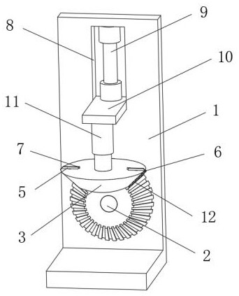
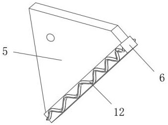
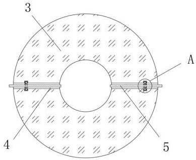
[0029] refer to Figure 1-4 , a bevel gear processing device for mechanical processing, comprising a fixed frame 1, the bottom of one end of the fixed frame 1 is rotatably connected with a horizontal positioning piece 2, and one end of the positioning piece 2 is rotatably connected with a rotating motor, and the fixed frame 1 is positioned on the positioning piece 2 is provided with a transmission part 3 that rotates horizontally, and the middle position of the top of the transmission part 3 is fixed with a driving motor 11, and the driving motor 11 is connected with a vertical displacement mechanism. Both sides of the outer wall of the transmission part 3 are provided with connecting grooves 4 , and the connecting piece 5 is connected by a spring between the inner walls of the two ends of the connecting groove 4, the top of the connecting piece 5 protrudes from the transmission part 3, and the position corresponding to the top of the transmission part 3 and the connecting piec...

Embodiment 2

[0037] refer to Figure 5-6 , a bevel gear processing device for mechanical processing, a chute 19 is provided at the middle position of the bottom of the fixed frame 1, and the chute 19 is arranged in parallel with the positioning member 2, and the inner wall of the chute 19 is slidably connected with a clamping plate 21, and the chute 19 One end of the bottom inner wall close to the positioning member 2 is provided with an embedding groove, the inner wall of the embedding groove is fixed with a magnetic block 20 , and the bottom of the clamping plate 21 is magnetically adsorbed to the magnetic block 20 .

[0038] When in use, when the bevel gear is installed on the positioning part 2, the vertically placed clamping plate 21 can be used to ensure the stability of the tooth groove position of the bevel gear, and ensure that the lowered transmission part 3 corresponds to the bevel gear, so as to ensure the stability of the device. actual use effect.


PUM


Abstract

The invention belongs to the technical field of machining, particularly discloses a bevel gear machining device for machining, and puts forward the following scheme now to solve the problems of poor deburring effect and low efficiency for inner walls of tooth grooves in bevel gears in the prior art. The device comprises a fixing frame; a horizontally-placed positioning piece is rotationally connected at the bottom of one end of the fixing frame; one end of the positioning piece is rotationally connected with a rotating motor; a horizontally-rotating transmission piece is arranged in the position, located above the positioning piece, of the fixing frame; and a driving motor is fixed to the middle of the top of the transmission piece. According to the device, a bevel gear and the transmission piece are rotated synchronously in a stepping manner, a striking piece extends into the corresponding tooth groove and vibrates and strikes the inner wall of the tooth groove along with a vibratingsheet, deburring operation is performed on the tooth groove of the inner wall of the bevel gear, after the transmission piece and the bevel gear are rotated by one circle, the transmission piece is paused, the bevel gear is rotated by the distance of one tooth groove gap, and deburring operation is performed on the tooth grooves in various positions of the bevel gear.

Description

technical field [0001] The invention relates to the technical field of mechanical processing, in particular to a bevel gear processing device for mechanical processing. Background technique [0002] The production process of a machine refers to the entire process of making a product from raw materials (or semi-finished products). For machine production, it includes transportation and storage of raw materials, preparation for production, manufacturing of blanks, processing and heat treatment of parts, assembly of products, and Debugging, painting and packaging, etc., the process of changing the size or performance of machine workpieces is machining. Bevel gears are a kind of workpieces, and they are often mechanically driven by a bevel gear set composed of multiple bevel gears. [0003] Generally used bevel gears are formed by the outer wall of the ring with interval distribution of ribs and tooth grooves. During the production and processing of bevel gears, burrs are often a...

Claims


Application Information

Patent Timeline
Patent Type & Authority Applications(China)
IPC IPC(8): B23F19/00B23F23/06
CPCB23F19/00B23F23/06
Inventor 郝明明王金燕
Owner 宣城知明灯机械设计有限公司
Why Eureka
Try Eureka