Automatic burr removing machining technology

A processing technology and deburring technology, which is applied to metal processing equipment, manufacturing tools, grinding workpiece supports, etc., can solve problems such as low work efficiency, incomplete burr removal, and large manual workload, so as to reduce workload and improve Work efficiency and deburring effect, complete deburring effect

Inactive Publication Date: 2019-07-05
SUZHOU JOYO METAL TECH CO LTD
View PDF11 Cites 5 Cited by
  • Summary
  • Abstract
  • Description
  • Claims
  • Application Information

AI Technical Summary

Problems solved by technology

The traditional deburring process is usually done manually by using tools such as files, sandpaper, blades, etc. The manual workload is large, the work efficiency is low, and the problem of incomplete deburring or scratches on the product surface often occurs

Method used


Image

  • Automatic burr removing machining technology
  • Automatic burr removing machining technology

Examples


Embodiment

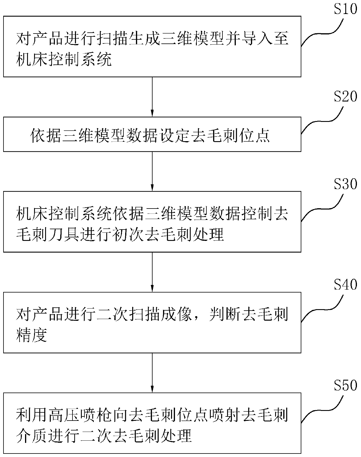
[0026] An automated deburring process, such as figure 1 shown, including the following steps:

[0027] S10, clamping and fixing the product to be processed on the automatic machine tool, scanning and identifying the surface of the product to be processed to generate a three-dimensional model of the product to be processed and importing it into the machine tool control system.

[0028] Specifically, first use the 3D imaging device connected to the machine tool control system to scan and image the product to be processed, and generate 3D model data based on the imaging information and import it into the machine tool control system. The 3D imaging device can use 3D imaging scanners and other equipment, and 3D modeling The equipment communicates with the machine tool control system through data lines or wireless networks;

[0029] After receiving the 3D model data, the machine tool control system establishes the processing coordinate system and generates the position information ...


PUM

PropertyMeasurementUnit
particle diameteraaaaaaaaaa

Abstract

The invention relates to an automatic burr removing machining technology. The technology comprises the steps that a product to be machined is fixedly clamped to an automatic machine tool, and the surface of the product to be machined is scanned and recognized so that a three-dimensional model of the product to be machined can be generated and guided into a machine tool control system; burr removing position points are set according to data of the three-dimensional model; the machine tool control system controls a burr removing cutter to cut or grind the burr removing position points accordingto the data of the three-dimensional model to carry out primary burr removing treatment; and a high-pressure spraying gun is utilized for spraying burr removing media to the burr removing position points to carry out burr removing treatment on the burr removing position points. According to the technology, the machine tool control system controls the burr removing cutter to be moved to carry out grinding and cutting, primary burr removing treatment is carried out on the product, then by means of the high-pressure spraying gun, the burr removing media are sprayed to the burr removing position points, the position, difficult to make contact, of the cutter is polished, thus the manual workload is reduced, and the working efficiency and the burr removing effect are removed.

Description

technical field [0001] The invention relates to the technical field of deburring equipment and technology, in particular to an automatic deburring process. Background technique [0002] After cutting and die-casting processes to form large-scale products, various burrs are usually generated on the surface of the product, so the product needs to be deburred. The traditional deburring process is usually done manually by using tools such as files, sandpaper, and blades. The manual workload is large, the work efficiency is low, and the problem of incomplete deburring or scratches on the product surface often occurs. Contents of the invention [0003] In order to solve the above technical problems, the present invention provides an automatic deburring process, which has the advantages of reducing manual workload, improving work efficiency and deburring effect. [0004] To achieve the above object, the technical scheme of the present invention is as follows: [0005] An automa...

Claims


Application Information

Patent Timeline
Patent Type & Authority Applications(China)
IPC IPC(8): B24B9/04B24B41/06B23D79/00
CPCB23D79/00B24B9/04B24B41/06
Inventor 程航宇
Owner SUZHOU JOYO METAL TECH CO LTD
Why Eureka
Try Eureka