Pipe cutting machine with deburring function

A technology of deburring and pipe cutting machine, which is applied in the direction of manufacturing tools, other manufacturing equipment/tools, transportation and packaging, etc. It can solve the problems of low production efficiency and long time consumption, and achieve high production efficiency, short time consumption and continuous Good results

Active Publication Date: 2017-07-21
浙江新诚汽车部件有限公司
View PDF9 Cites 5 Cited by
  • Summary
  • Abstract
  • Description
  • Claims
  • Application Information

AI Technical Summary

Problems solved by technology

At present, the two processes of pipe cutting and deburring are completed by the pipe cutting machine and the deburring machine respectively. After the pipe cutting is completed, the material needs to be unloaded and then loaded into the deburring machine. It takes a long time and the production efficiency is low.

Method used


Image

  • Pipe cutting machine with deburring function
  • Pipe cutting machine with deburring function
  • Pipe cutting machine with deburring function

Examples


Embodiment 1

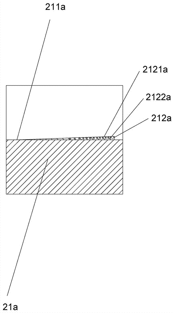
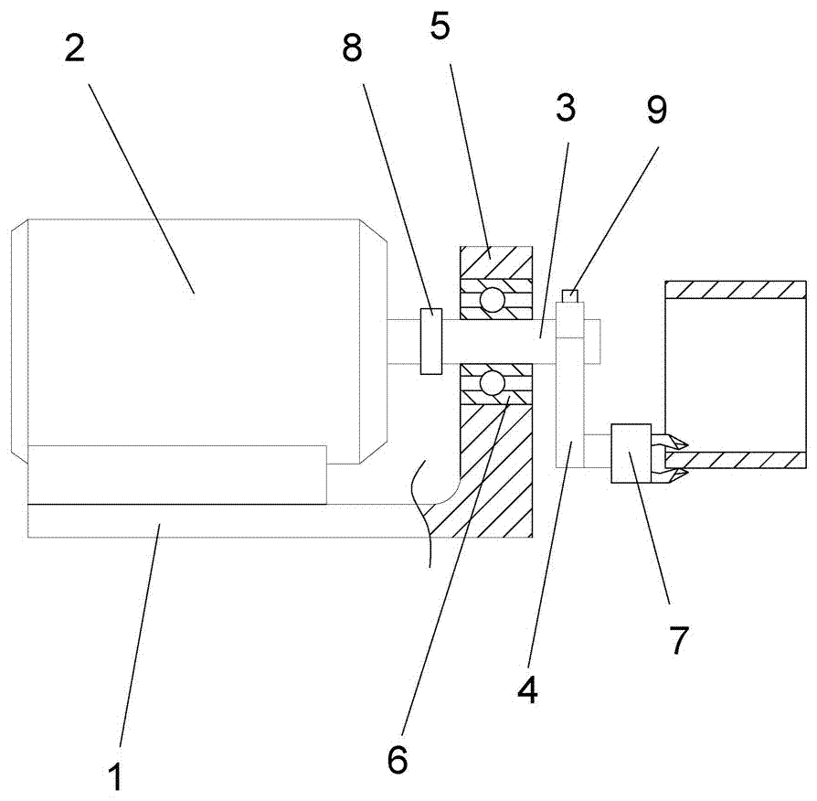
[0035] Embodiment 1: as Figure 1-Figure 7 As shown, a pipe cutting machine with deburring includes a frame 1a, an exhaust pipe clamping device 2a arranged on the frame 1a, and an exhaust pipe clamping device 2a arranged on the frame 1a. The cutting mechanism 3a above the clamping device 2a that can approach or move away from the exhaust pipe is characterized in that the exhaust pipe clamping device 2a includes a first clamping seat 21a, which can be close to or away from the first clamping seat The second clamping seat 22a of 21a also includes the two sides of the cutting mechanism 2a which are arranged on the frame 1a and can be close to or away from the first clamping seat 21a and the second clamping seat respectively. 22a deburring device, the first detection mechanism installed on the frame 1a for detecting whether the cutting mechanism 3a cuts off the exhaust pipe, drives the second clamping seat 22a away from or close to the first The first driving mechanism of the cla...

Embodiment 2

[0046] Embodiment 2: In order to improve the shaping effect, the mouth of the exhaust pipe can be properly heated to increase the deformability at the mouth of the pipe. Preferably, the device also includes a heating device, and the heating device can adopt a heat gun or an electric heating device. Heating wire. Therefore, the heating device can indirectly improve the deburring efficiency.

[0047] All the other are with embodiment 1.

Embodiment 3

[0048] Embodiment 3: A weight block 9 is fixedly arranged at the end of the rotating handle 4 away from the deburring tool 7 . The weight block 9 makes the center of mass of the turning handle 4 approach the center of rotation as much as possible, and the turning handle 4 rotates more stably. Correspondingly, the deburring cutter 7 is just more stable, and the deburring effect is just better. All the other are with embodiment 1.


PUM


Abstract

The invention discloses a pipe cutting machine with a deburring function. The pipe cutting machine comprises a rack, an exhaust pipe clamping device arranged on the rack and a cutting mechanism which is arranged on the rack, located above the exhaust pipe clamping device and has the function of being close to or away from an exhaust pipe. The exhaust pipe clamping device comprises a first clamping seat and a second clamping seat capable of being close to or away from the first clamping seat and furthermore comprises a deburring device arranged on the rack, a first detection mechanism, a first drive mechanism, a second detection mechanism and a pair of second drive mechanisms, wherein the first detection mechanism is arranged on the rack and is used for detecting whether the cutting mechanism cuts off the exhaust pipe or not, the first drive mechanism is used for driving the second clamping seat to be away from or close to the first clamping seat, the second detection mechanism is used for detecting whether the second clamping seat is moved in place or not, and the second drive mechanisms are used for driving the deburring device to be close to or away from the first clamping seat and the second clamping seat correspondingly. After pipe cutting is completed, the deburring action is performed immediately, continuity is good, the process of unloading on the pipe cutting machine and the process of loading on a deburring machine are omitted, time consumption is short, and production efficiency is high.

Description

technical field [0001] The invention relates to the field of pipe cutting machines, and more specifically relates to a pipe cutting machine with deburring. Background technique [0002] In the automobile industry, after the exhaust pipe is cut by a pipe cutting machine, burrs will appear at the nozzle, and workers need to remove the burrs. At present, the two processes of pipe cutting and deburring are completed by the pipe cutting machine and the deburring machine respectively. After the pipe cutting is completed, the material needs to be unloaded and then loaded into the deburring machine. The process takes a long time and the production efficiency is low. Contents of the invention [0003] Aiming at the defects of the prior art, the object of the present invention is to provide a pipe cutting machine with deburring. After the pipe cutting is completed, the deburring action is performed immediately, and the continuity is good, and the unloading on the pipe cutting mach...

Claims


Application Information

Patent Timeline
Patent Type & Authority Applications(China)
IPC IPC(8): B23P23/02B23P23/04
CPCB23P23/02B23P23/04B23P2700/50
Inventor 张健赵博韬
Owner 浙江新诚汽车部件有限公司
Why Eureka
Try Eureka