L-shaped slotted hole machining method based on PCB

A processing method and technology of slot holes, which are applied in the direction of electrical components, printed circuit manufacturing, printed circuits, etc., can solve the problems of lost man-hours and losses, and achieve the effects of improving the overall quality, avoiding burrs, and enhancing the effect of deburring

Active Publication Date: 2020-04-14
广州广合科技股份有限公司
View PDF7 Cites 5 Cited by
  • Summary
  • Abstract
  • Description
  • Claims
  • Application Information

AI Technical Summary

Problems solved by technology

There will be burrs at the corners, and subsequent processing of the burrs is required, which not only wastes man-hours, but also brings unnecessary losses due to the breakage rate of the subsequent processing.

Method used


Image

  • L-shaped slotted hole machining method based on PCB
  • L-shaped slotted hole machining method based on PCB
  • L-shaped slotted hole machining method based on PCB

Examples


Embodiment 1

[0035] A method for machining L-shaped slots based on PCB, characterized in that, comprising the steps:

[0036] S1. Divide the L-shaped slot into horizontal slots and longitudinal slots according to the processing steps, establish a plane Cartesian coordinate system with the intersection of the two slots as the origin to form four quadrants, and determine the gap between the horizontal slot and the longitudinal slot. The quadrant of the angle;

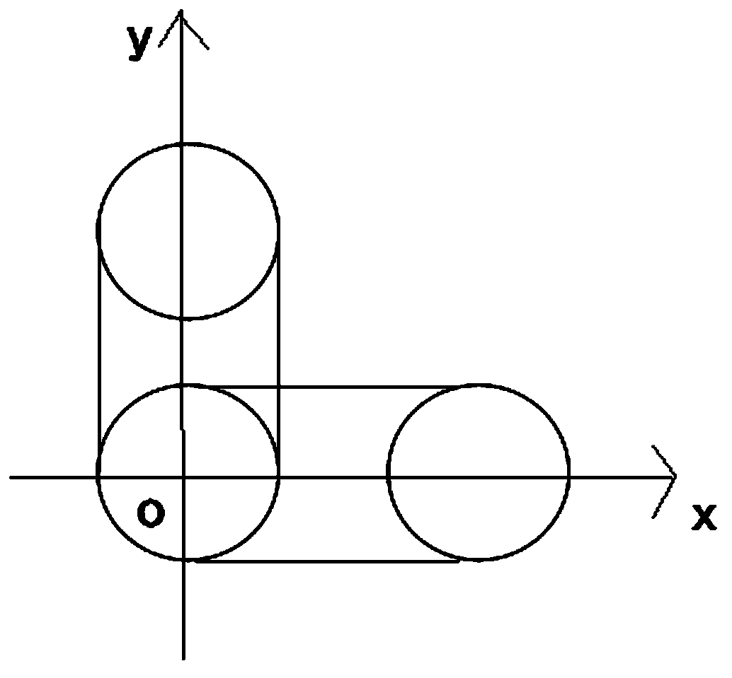
[0037] S2, according to the judgment in the S1 step, if the angle formed by the transverse slot and the longitudinal slot is in the first quadrant, the processing sequence is to process the longitudinal slot first, and then process the transverse slot;

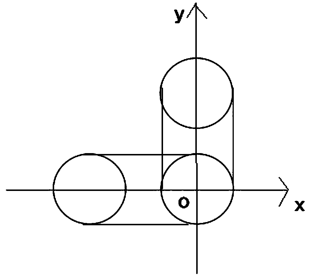
[0038] S3, according to the judgment in the step S1, if the angle formed by the transverse slot and the longitudinal slot is in the second quadrant, the processing sequence is to process the transverse slot first, and then process the longitudinal slot;

[0039] S4, according to the ...

Embodiment 2

[0045] On the basis of embodiment 1, technical scheme has been carried out automatic improvement, and its concrete improvement scheme is as follows:

[0046] The rotation direction of the tool is set in the drill belt parameter as clockwise rotation.

[0047] For the L-shaped groove located in the first quadrant, the tool path for making the drill tape is: from the end of the longitudinal slot far away from the origin, the tool is fed to the origin to complete the longitudinal slot, and then the tool is fed from the origin to the positive direction of the X axis Complete the horizontal slot.

[0048] For the L-shaped groove located in the second quadrant, the tool path for making the drill tape is: from the end of the horizontal slot far away from the origin, the tool is fed to the origin to complete the horizontal slot, and then the tool is fed from the origin to the positive direction of the Y axis Complete the longitudinal slot.

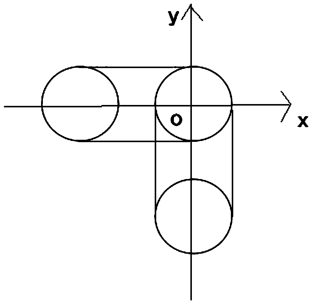
[0049] For the L-shaped groove located in...

Embodiment 3

[0053] On the basis of embodiment 1 or embodiment 2, technical scheme has been improved as follows:

[0054] The tool path for making the drill tape is as follows: each slot hole is firstly slotted and then slotted.

[0055] The tool diameter of the grooving tool is 1.1 mm.

[0056] The diameter of the expanding tool is 1.3mm.

[0057] The tool path for making the drill tape is: After completing the slotting process and expanding process of the horizontal slot hole / longitudinal slot hole of the L-shaped slot hole, after obtaining the complete slot hole, proceed to the longitudinal slot hole / horizontal slot hole processing process .

[0058] In order to make the size of the slot hole more accurate and ensure the side wall of the slot hole to be smoother, the slotting process of the unidirectional slot hole is divided into two steps: the slotting process and the slotting process. While improving the quality of the slot hole, it can more effectively avoid the generation of bur...


PUM


Abstract

The invention provides an L-shaped slotted hole processing method based on a PCB, and the method comprises the following steps: splitting an L-shaped slotted hole into a transverse slotted hole and alongitudinal slotted hole according to the processing steps, building a rectangular plane coordinate system with the intersection point of the two slotted holes as an original point to form four quadrants, and judging the quadrant where an included angle formed by the transverse slotted hole and the longitudinal slotted hole is located; if in the first quadrant, realizing the condition that the machining sequence is that the longitudinal slotted hole is firstly machined and then the transverse slotted hole is machined; if in the second quadrant, realizing the condition that the machining sequence is that the transverse slotted hole is firstly machined and then the longitudinal slotted hole is machined; if in the third quadrant, realizing the condition that the machining sequence is that the longitudinal slotted holes are machined firstly and then the transverse slotted holes are machined; if in the fourth quadrant, realizing the condition that the machining sequence is that the transverse slotted hole is firstly machined and then the longitudinal slotted hole is machined; manufacturing a drill belt; and dividing the L-shaped slotted hole into two sections of one-way slotted holes to be slotted. A special cutter path is arranged, so that burrs are avoided.

Description

technical field [0001] The invention belongs to the field of PCB circuit board manufacturing, and in particular relates to a PCB-based L-shaped slot hole processing method. Background technique [0002] PCB (Printed Circuit Board), the Chinese name is printed circuit board, also known as printed circuit board, is an important electronic component, a support for electronic components, and a carrier for electrical connections of electronic components. Because it is made using electronic printing, it is called a "printed" circuit board. During the plate-making process of the PCB board, a large number of drilling holes are required to match the package original or the internal circuit connection of the PCB board, including L-shaped slot holes. [0003] The L-shaped slot needs to be slotted twice successively, and the two slots intersect at one place to form a corner. Burrs will be generated at the corners, and subsequent processing of the burrs is required, which not only wast...

Claims


Application Information

Patent Timeline
Patent Type & Authority Applications(China)
IPC IPC(8): H05K3/00
CPCH05K3/0044H05K3/0047
Inventor 钟根带巩杰麦美环王平
Owner 广州广合科技股份有限公司
Why Eureka
Try Eureka