HDPE corrugated pipe rapid clamping device and using method thereof

A clamping device and bellows technology, which is applied to grinding drive devices, machine tools suitable for grinding workpiece edges, grinders, etc., can solve the problem of poor deburring effect of HDPE bellows, poor grinding effect, and slippage. and other problems, to achieve the effect of improving the efficiency of grinding and deburring, good deburring effect and good fixing effect

Inactive Publication Date: 2021-04-02
RONGCHENG PIPE IND
View PDF6 Cites 5 Cited by
  • Summary
  • Abstract
  • Description
  • Claims
  • Application Information

AI Technical Summary

Problems solved by technology

And because the connection is convenient and reliable, it has been widely used at home and abroad, replacing concrete pipes and cast iron pipes in large quantities. Often, HDPE corrugated pipes have burrs on the end faces after cutting, and cannot be put into use directly. A grinding device is required for port deburring.
[0003] However, HDPE corrugated pipes often need to be clamped and positioned when they are polished, and the existing clamps are more complicated to operate when clamping, resulting in the pipe fittings being very likely to slip during the grinding process, resulting in poor grinding effects. After the HDPE corrugated pipe is clamped and fixed, the distance between it and the grinding disc cannot be adjusted again. When the distance between the HDPE corrugated pipe and the grinding disc is improper, the deburring effect of the HDPE corrugated pipe will deteriorate again, which will affect the quality of the pipe fittings. Production and processing efficiency needs to be improved urgently

Method used


Image

  • HDPE corrugated pipe rapid clamping device and using method thereof
  • HDPE corrugated pipe rapid clamping device and using method thereof
  • HDPE corrugated pipe rapid clamping device and using method thereof

Examples


Embodiment Construction

[0033] In order to enable those skilled in the art to better understand the technical solutions of the present invention, the present invention will be further described in detail below in conjunction with the accompanying drawings.

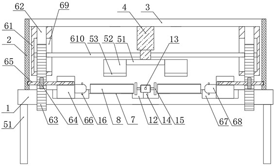
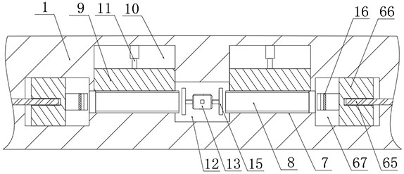
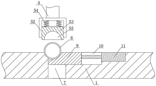
[0034] The present invention provides such Figure 1-3 The HDPE corrugated pipe quick clamping device shown includes a bottom plate 1, a vertical plate 2 is fixed on both sides of the top of the bottom plate 1, and a horizontal plate is fixedly connected to the adjacent side surfaces of the two vertical plates 2 3. The bottom of the horizontal plate 3 is fixed with a first cylinder 4, the bottom of the output end of the first cylinder 4 is provided with a clamping mechanism, and the left and right sides of the output end of the first cylinder 4 are provided with a pushing mechanism;

[0035] Described clamping mechanism comprises first connecting rod 51, and described first connecting rod 51 is fixedly arranged on the bottom of the output end of ...


PUM


Abstract

The invention discloses an HDPE corrugated pipe rapid clamping device and a using method thereof. The device comprises a bottom plate, vertical plates are fixedly arranged at the two sides of the topof the bottom plate correspondingly, a transverse plate is fixedly connected to the surfaces of the adjacent sides of the two vertical plates, a first air cylinder is fixedly arranged at the bottom ofthe transverse plate, and a clamping mechanism is arranged at the bottom of the output end of the first air cylinder; and pushing mechanisms are arranged at the left side and the right side of the output end of the first air cylinder correspondingly, and the clamping mechanism comprises a first connecting rod. A clamping plate is pushed by a second air cylinder to be matched with the bottom plateto form a semicircular through hole used for containing a corrugated pipe body, under the action of a first air cylinder, clamping and fixing of the corrugated pipe body are completed while the distance between the corrugated pipe body and a grinding disc is adjusted, the distance is accurately controlled, the positioning speed is high, and the fixing effect is good; and the sliding phenomenon cannot occur during grinding, so that the grinding and deburring efficiency of the corrugated pipe body is greatly improved, and the deburring effect is good.

Description

technical field [0001] The invention relates to the technical field of clamping and cutting pipes, in particular to a fast clamping device for HDPE corrugated pipes and a method for using the same. Background technique [0002] HDPE corrugated pipe is a new type of lightweight pipe made of high-density polyethylene. It has the characteristics of light weight, high pressure resistance, good toughness, fast construction, and long life. Its excellent pipe wall structure design is different from other structural pipes. In comparison, the cost is greatly reduced. And because of the convenient and reliable connection, it has been widely used at home and abroad, replacing concrete pipes and cast iron pipes in large quantities. Often, HDPE corrugated pipes have burrs on the end faces after cutting, and cannot be put into use directly. A grinding device is required to deburr the ports. [0003] However, HDPE corrugated pipes often need to be clamped and positioned when they are poli...

Claims


Application Information

Patent Timeline
Patent Type & Authority Applications(China)
IPC IPC(8): B24B9/20B24B41/04B24B41/06B24B47/12B24B47/20B24B47/22
CPCB24B9/20B24B41/061B24B47/22B24B41/04B24B47/12B24B47/20
Inventor 虞敏朱加荣
Owner RONGCHENG PIPE IND
Why Eureka
Try Eureka