Lifting valve device for dust collector
A lift valve and dust collector technology, applied in chemical instruments and methods, dispersed particle separation, dispersed particle filtration, etc., can solve the problems of unadjustable energy consumption, large diameter of the lifting cylinder, etc., to achieve energy-saving service life, reduce energy consumption, The effect of improving dust removal efficiency
- Summary
- Abstract
- Description
- Claims
- Application Information
AI Technical Summary
Problems solved by technology
Method used
Image

Examples
Embodiment Construction
[0016] Below in conjunction with accompanying drawing, specific embodiment of the present invention is described in further detail:
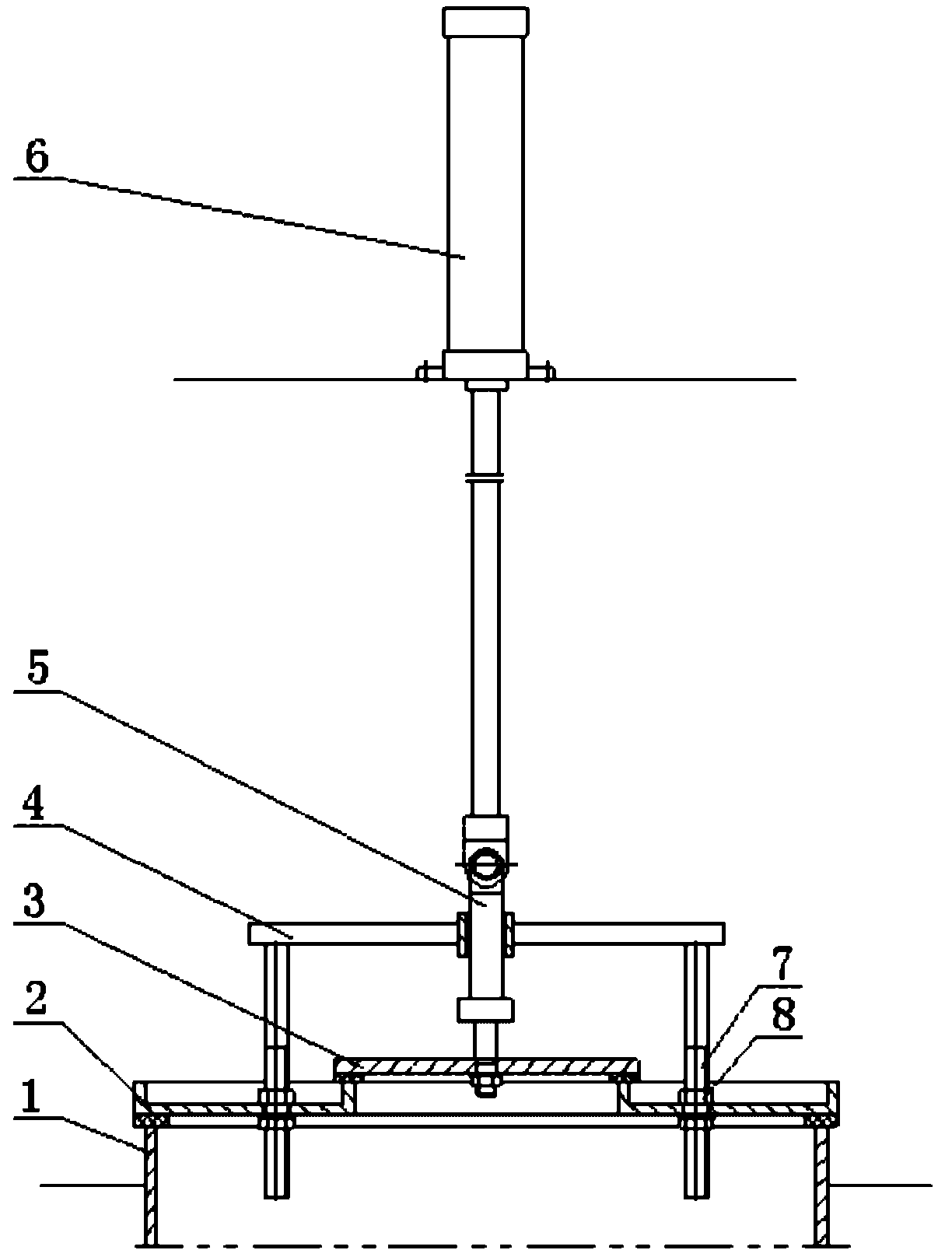
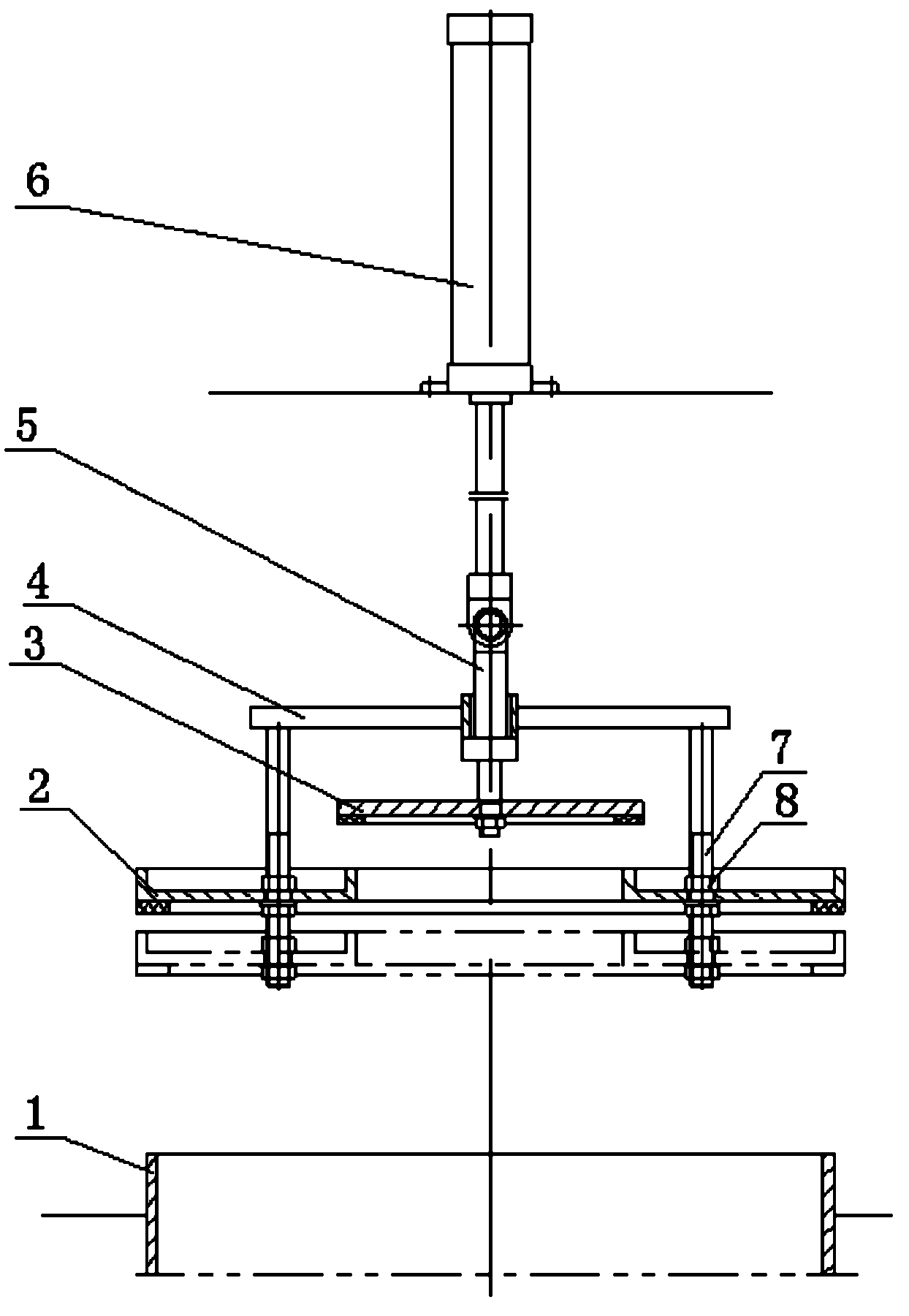
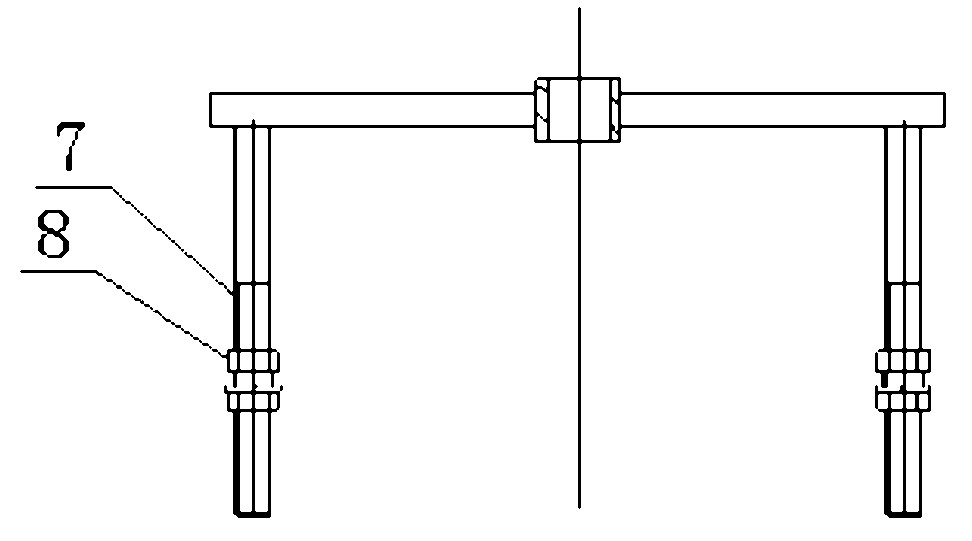
[0017] Such as figure 1 and 2 As shown, it is a structural schematic diagram of an embodiment of the present invention, the device includes a lifting mechanism 6, a valve stem 5, a first valve plate 3 and a second valve plate 2, and the lifting mechanism 6 is connected with the valve stem 5 The first valve plate 3 is connected, the outside of the first valve plate 3 is provided with a second valve plate 2 and a lift adjustment structure 4, and the upper part of the second valve plate 2 is connected with the lift adjustment structure 4 to form a sealed space , so that the first valve plate 3 is accommodated in the sealed space. The poppet valve device of the dust collector of the present invention is installed between the filter chamber (i.e., the clean air chamber) and the air outlet pipeline of the dust collector. The second valve plate 2 is ...
PUM
 Abstract
Description
Claims
Application Information
 - R&D
- Intellectual Property
- Life Sciences
- Materials
- Tech Scout
- Unparalleled Data Quality
- Higher Quality Content
- 60% Fewer Hallucinations
Browse by: Latest US Patents, China's latest patents, Technical Efficacy Thesaurus, Application Domain, Technology Topic, Popular Technical Reports.
© 2025 PatSnap. All rights reserved.Legal|Privacy policy|Modern Slavery Act Transparency Statement|Sitemap|About US| Contact US: help@patsnap.com