Milling machine clamp for shell components
A milling machine fixture and parts technology, which is applied in the direction of milling machine equipment, milling machine equipment details, metal processing machinery parts, etc., can solve the problems of increasing fixture design and manufacturing costs, production preparation cycle, high labor intensity, and low production efficiency, so as to reduce production The effect of preparing cycle, reducing labor intensity and improving production efficiency
- Summary
- Abstract
- Description
- Claims
- Application Information
AI Technical Summary
Problems solved by technology
Method used
Image

Examples
Embodiment Construction
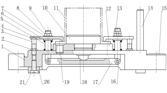
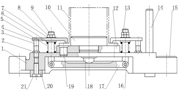
[0014] A milling machine fixture for shell parts according to the present invention, see figure 1 , the milling machine clamp includes clamp body 1, lock nut 2, support nail 3, left pressure plate 41, right pressure plate 42, compression spring 5, directional key 20, positioning plate 12, left rotation lever 91, right rotation lever 92, cylindrical pin 10, lever 17 and bearing 18. The orientation key 20 is fixed on the fixture body 1 by a screw 21, and is used to determine the position of the milling fixture relative to the machine tool The milling machine clamp is fastened on the milling machine workbench at the position of the lug seat 15 of the clamp body 1 through bolts; the positioning plate 12 is connected with the clamp body 1 through screws 19 . The cylindrical pin 10 is connected with the positioning plate 12, wherein the cylindrical pin 10 can be The radial basic dimension of the hole Make a replacement. The tool setting block 14 is threadedly connected to the c...
PUM
 Abstract
Description
Claims
Application Information
 - R&D
- Intellectual Property
- Life Sciences
- Materials
- Tech Scout
- Unparalleled Data Quality
- Higher Quality Content
- 60% Fewer Hallucinations
Browse by: Latest US Patents, China's latest patents, Technical Efficacy Thesaurus, Application Domain, Technology Topic, Popular Technical Reports.
© 2025 PatSnap. All rights reserved.Legal|Privacy policy|Modern Slavery Act Transparency Statement|Sitemap|About US| Contact US: help@patsnap.com