
Rotating around optical axis alignment error analysis method

A technology of alignment error and optical axis rotation, applied in the direction of using optical devices, measuring devices, instruments, etc., can solve the problems of complex structure and device, difficult to realize, and difficult to adjust, so as to simplify the detection device and improve the alignment accuracy. Effect

Inactive Publication Date: 2013-12-04
INST OF OPTICS & ELECTRONICS - CHINESE ACAD OF SCI
View PDF3 Cites 0 Cited by
  • Summary
  • Abstract
  • Description
  • Claims
  • Application Information

AI Technical Summary

Problems solved by technology

The existing method is to design a precise eight-dimensional adjustment frame (Karl Edmund Flssner, R Burow, J Grzanna, et al. "Absolute sphericity measurement," Appl Opt.28, 4649-4661, 1989), relying on the precision of the eight-dimensional adjustment frame The mechanical structure of the measured optical element is used to control the tilt and eccentricity of the optical element under test generated during the rotation process. This method has a complex structure and device, and with the increase of the numerical aperture of the optical element under test, the adjustment difficulty gradually increases, and it is not easy to realize.

Method used


Image

  • Rotating around optical axis alignment error analysis method
  • Rotating around optical axis alignment error analysis method
  • Rotating around optical axis alignment error analysis method

Examples


Embodiment Construction

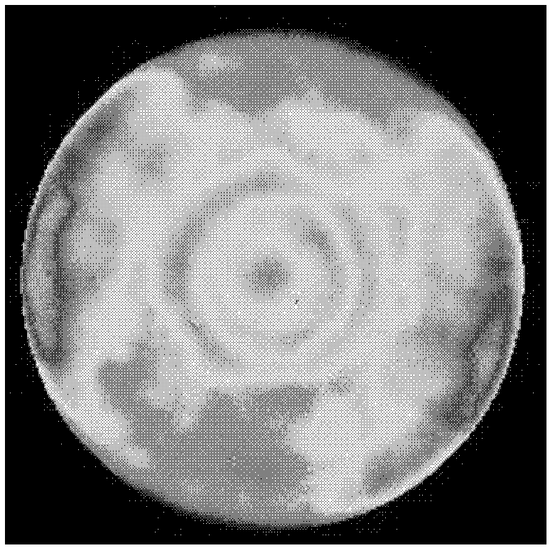
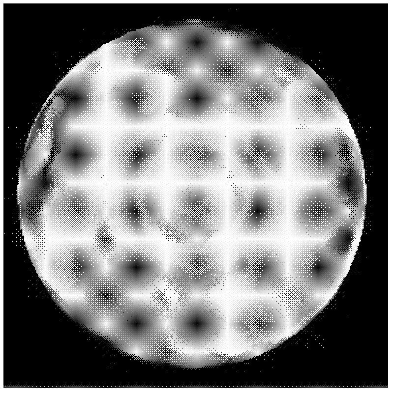
[0036] The specific implementation method is combined with the attached Figure 2-4 to illustrate.

[0037] The procedure for the analysis of alignment errors when rotating around the optical axis in absolute detection:

[0038] 1) Adjust the detection device of the optical element under test so that the optical element under test and the reference surface are in a confocal position, that is, the centers of curvature of the two coincide. At this time, M times (M can be taken as 50) repeated measurements are carried out on the optical element under test; according to the PV and RMS values ​​of the measured data, PV refers to the difference between the maximum value and the minimum value in the surface shape data, and RMS refers to the surface shape data. The root mean square value of the data, the gross error elimination principle, the Leite criterion, the gross error in the M measurement data is eliminated, and the average result of all the measurement data (M1 times) after t...


PUM


Abstract

The invention discloses a rotating around optical axis alignment error analysis method. The method comprises the following steps: carrying out zernike stripe polynomial fitting on measured surface data at an initial position, extracting a fitting coefficient of a rotational symmetry entry; rotating a detected optical element around an optical axis to a certain angle, carrying out zernike stripe polynomial fitting on measured surface data and extracting a coefficient of a rotational symmetry entry same, carrying out a difference operation on the coefficient and a corresponding polynomial fitting coefficient before rotation, comparing an operation result with an obtained threshold through fitting, and obtaining rotating around optical axis alignment error information. Many times of alignment of different rotation angles and positions are carried out repeatedly in this way. The invention provides the rotation aligning error analysis method, a quantitative analysis method is provided for rotation alignment error control in absolute detection, and the invention has a large application value for reducing a rotation alignment error and raising surface absolute detection precision.

Description

technical field [0001] The invention relates to a method for analyzing alignment errors around an optical axis, and belongs to the field of advanced optical manufacturing and detection. Background technique [0002] With the rapid development of modern industrial technology, the requirements for surface accuracy of optical components are constantly increasing. Fizeau-type phase-shifting interferometer is the main means of high-precision surface shape detection at present, and the surface shape error of the measured optical element obtained by its detection is relative to the standard surface shape of the reference surface, and the detection accuracy is limited by the reference surface. surface accuracy and system error, while the absolute detection technology can remove the system error through the mutual operation processing of multiple detection data, and obtain the absolute surface shape of the measured optical element that is not affected by the surface shape accuracy of...

Claims


Application Information

Patent Timeline
Patent Type & Authority Patents(China)
IPC IPC(8): G01B11/24
Inventor 侯溪宋伟红伍凡吴永前万勇建
Owner INST OF OPTICS & ELECTRONICS - CHINESE ACAD OF SCI
Learn More