

System and method for improving RB working condition of induced draft fans of two-boiler one-machine thermal power generating unit
A technology of thermal power units and induced draft fans, which is applied in the directions of induced air, combustion methods, and air supply adjustment, which can solve problems such as secondary air volume reduction, coal powder retention, and severe fluctuations in furnace negative pressure, so as to reduce the probability of equipment damage, The effect of delaying the process of withdrawing from the furnace and shortening the process time
- Summary
- Abstract
- Description
- Claims
- Application Information
AI Technical Summary
Problems solved by technology
Method used
Image

Examples
Embodiment
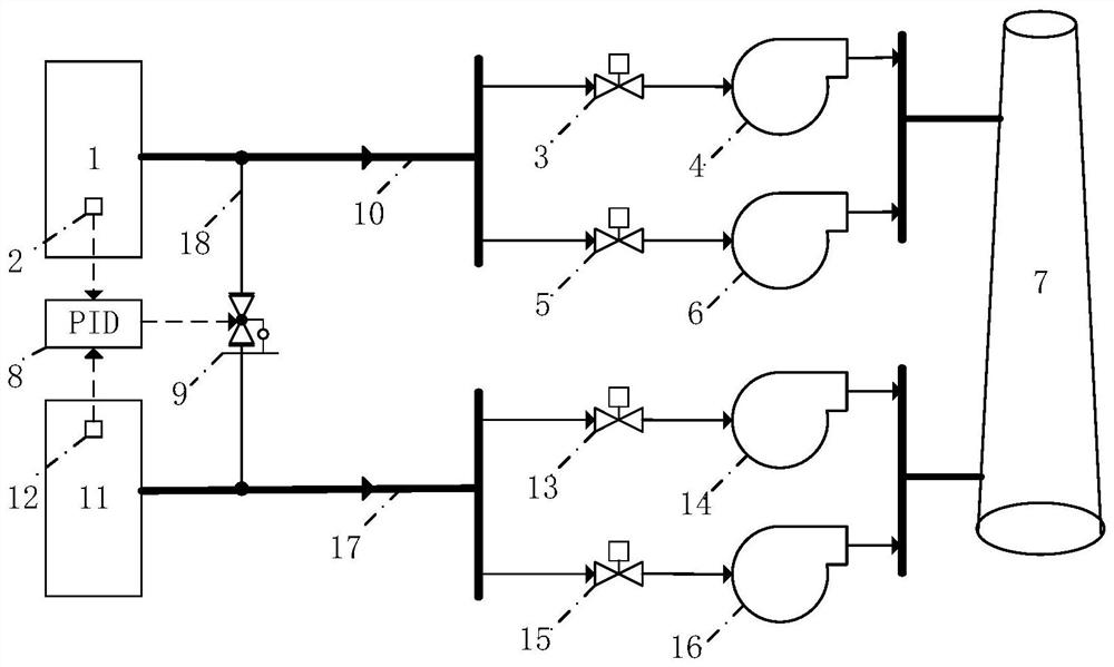
[0041] Such as figure 1 As shown, taking the fault trip of the first induced draft fan 4, which triggers the induced draft fan RB of the two furnaces and one machine unit, the unit operates at 100% rated load before RB triggers, and the other three induced draft fans are normal. The role of induced draft fan RB process in furnace one machine thermal power unit.
[0042]When the first induced draft fan 4 fails and trips, and the induced draft fan RB of two boilers and one unit is triggered, the second boiler 11 does not need to trip one induced draft fan at the same time, and will not trigger the induced draft fan RB working condition like the first boiler 1. After an induced draft fan 4 trips, while the first valve 3 at the input end of the first induced draft fan 4 is closed, the electric regulating valve 9 on the communication pipe 18 between the first induced draft main pipe 10 and the second induced air main pipe 17 is supplied. Directly open to 80% (reserve a certain adj...
PUM
 Abstract
Description
Claims
Application Information