
Framework-type support component for wind tunnel test model

A technology for supporting members and wind tunnel testing, which is used in aerodynamic testing, testing of machine/structural components, measuring devices, etc., and can solve problems such as deficiencies, the influence of supporting members on wind tunnel airflow, and the rigidity of large supporting members. Achieve the effect of reducing self-weight, reducing deformation, and improving support stiffness

Inactive Publication Date: 2012-06-13
INST OF HIGH SPEED AERODYNAMICS OF CHINA AERODYNAMICS RES & DEV CENT
View PDF6 Cites 15 Cited by
  • Summary
  • Abstract
  • Description
  • Claims
  • Application Information

AI Technical Summary

Problems solved by technology

[0005] For the domestic high-speed wind tunnel test model, when the traditional support member rotates in the side-slip direction, the windward area will be greatly increased, which will have a greater impact on the blockage of the wind tunnel flow field, and under the action of high-speed aerodynamic force, the traditional support member solid The support deformation of the plate is very large, and the rigidity is seriously insufficient. However, only by increasing the thickness of the solid blade of the support member to increase the support rigidity will cause further increase in the airflow blockage of the wind tunnel, which will inevitably lead to increased interference of the support member on the wind tunnel flow field. Problem, the present invention provides a skeleton-type wind test model support member for high-speed wind tunnel tests, which can well solve the problem that the support member has a great influence on the airflow blockage of the wind tunnel when the wind tunnel is used for variable sideslip direction angle tests problems and insufficient stiffness of support members under high-speed aerodynamic loads

Method used


Image

  • Framework-type support component for wind tunnel test model
  • Framework-type support component for wind tunnel test model
  • Framework-type support component for wind tunnel test model

Examples


Embodiment Construction

[0019] The present invention will be further described below in conjunction with the accompanying drawings.

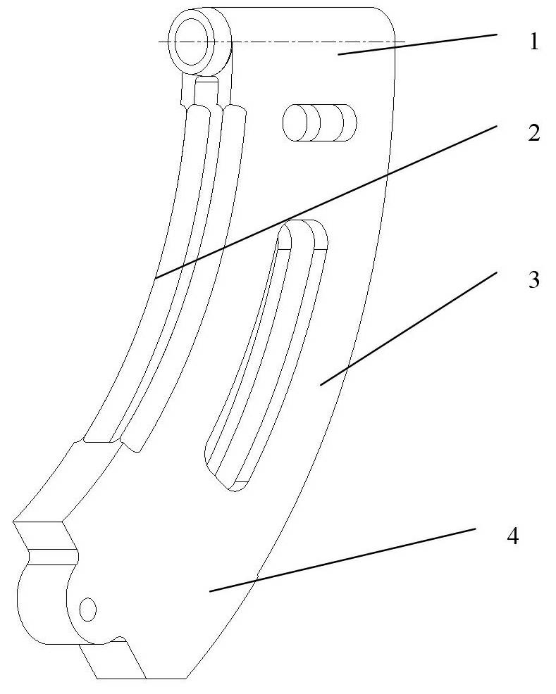
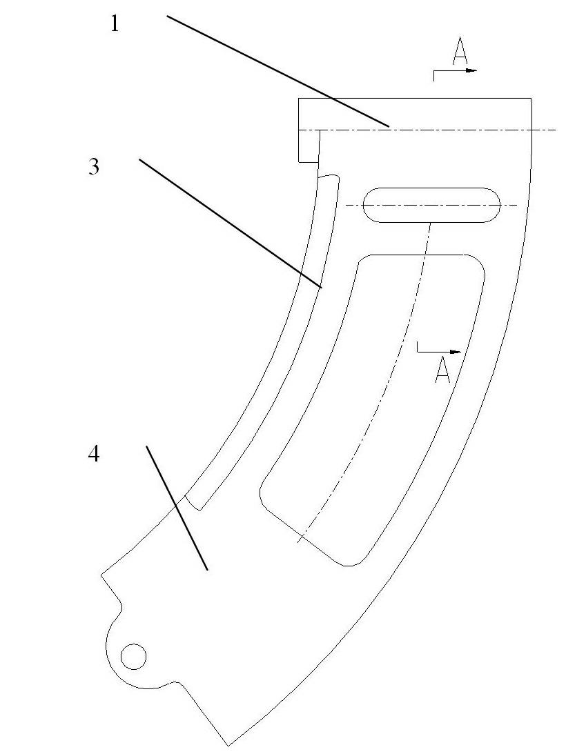
[0020] like figure 1 , figure 2 , image 3 , Figure 4 As shown, the skeleton-type wind tunnel test model support member of the present invention is composed of a middle bracket 1, a left support plate 2, a right support plate 3, and a lower connecting seat 4. Angle type, under the action of the driving mechanism, the support member can make up and down pitching motion and horizontal side sliding direction rotation. Two upper discharge holes are arranged symmetrically on the left and right sides of the middle support 1; the left support plate 2 and the right support plate 3 are respectively connected with the middle support 1, and two lower discharge holes are symmetrically arranged on the left support plate 2 and the right support plate 3; The lower connection base 4 connects the left support plate 2 and the right support plate 3 as a whole, and the lower connect...


PUM


Abstract

The invention belongs to the technical field of aerodynamic wind tunnel test, and provides a framework-type support component for a wind tunnel test model. The support component is of a sector framework-type support structure comprising a middle support, a left support plate, a right support plate and a lower connecting seat, a discharge channel is arranged in the middle of the support component, discharge holes are arranged on the left and the right of the support component, and a windward side is provided with a windward airflow closed angle. When in a wind tunnel test, airflow can pass through a framework, so that airflow blockage due to a support device is decreased. The support component is capable of solving the problem that a test model support component greatly blocks airflow and is insufficient in rigidity under the action of high-speed aerodynamic force when a wind tunnel is in a lateral-directional model test.

Description

technical field [0001] The invention belongs to the technical field of aerodynamic wind tunnel tests, and in particular relates to a skeleton-type wind tunnel test model support member, which is used for the support of the wind tunnel test model and the adjustment of attitude angles. Background technique [0002] The supporting member of the wind tunnel test model mainly plays the role of supporting the test model and changing the attitude angle (pitch direction angle and sideslip direction angle) of the model in the wind tunnel. During the wind tunnel test, the test model is installed and fixed on the support member, and the attitude angle of the model is changed by changing the state of the support member, so as to obtain the test data of the test model in different model attitude angle states in the wind tunnel. The supporting member of the wind tunnel test model is a steel structure. In order to ensure the safety of the supporting member and the accuracy of the attitude ...

Claims


Application Information

Patent Timeline
IPC IPC(8): G01M9/04
Inventor 张峻篈师建元陈德华易凡范长海毛代勇薛江平龙秀虹
Owner INST OF HIGH SPEED AERODYNAMICS OF CHINA AERODYNAMICS RES & DEV CENT
Learn More