

Flexible rope simulation method
A simulation method and rope technology, which is applied in the field of rope simulation, can solve the problems of insufficient fidelity, complex code, and inability to fully cover the motion characteristics of the rope, and achieve the effect of high simulation degree and concise code
- Summary
- Abstract
- Description
- Claims
- Application Information
AI Technical Summary
Problems solved by technology
Method used
Image

Examples
Embodiment Construction
[0039] The present invention will be further described below in conjunction with the accompanying drawings and embodiments.
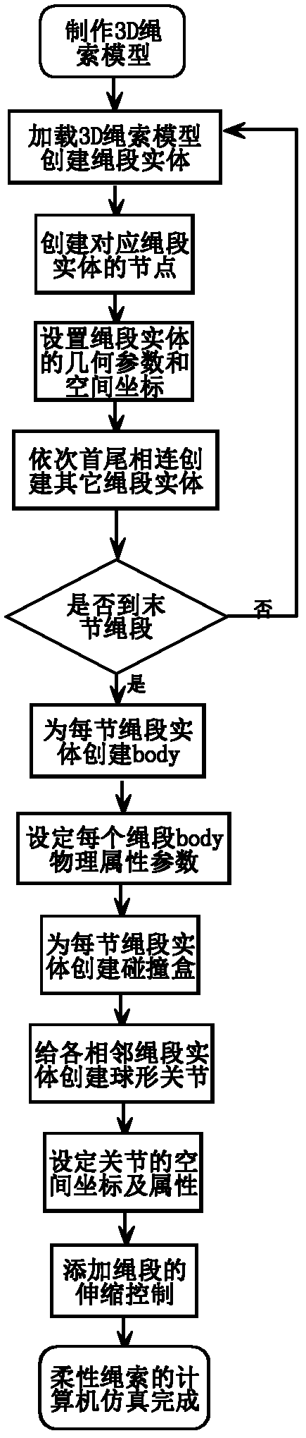
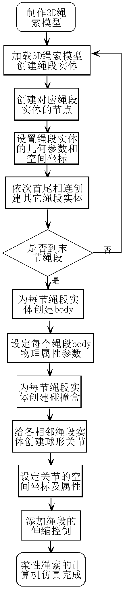
[0040] Such as figure 1 , figure 2 Shown, the concrete process of method of the present invention is:
[0041] Step 1: Make a 3D rope model (a model file in mesh format that can be used by a physics engine)
[0042] The 3D model maker uses 3DMax software to create a model file in the format of .mesh. This type of model file contains information such as the local coordinate system of the model in the engine simulation scene and its texture.
[0043] Step 2: Load the 3D model file we made in the engine simulation scene to create a rope segment entity.
[0044] Entity: The model (geometric information) of the rope segment in the engine simulation scene.
[0045] Step 3: Create a node corresponding to the rope segment, which is used to modify the geometric information and spatial coordinates of the set entity.
[0046] The association of models in the...
PUM
 Abstract
Description
Claims
Application Information