
Cutting plotter

A cutting and plotting machine and cutting processing technology, which is applied in the field of cutting and plotting machines, can solve the problems of inability to process medium cutting, inability to move the carriage straightly, deterioration of the quality of the processed medium, etc., and achieve the effect of preventing quality deterioration

Inactive Publication Date: 2012-06-13
MIMAKI ENG
View PDF6 Cites 5 Cited by
  • Summary
  • Abstract
  • Description
  • Claims
  • Application Information

AI Technical Summary

Problems solved by technology

When cutting using the curved first guide rail or second guide rail, it goes without saying that the carriage cannot be moved straight along the guide rail, and the workpiece cannot be cut into the desired shape. Problem, there is a problem that the quality of the cutting process of the processed medium deteriorates

Method used


Image

  • Cutting plotter
  • Cutting plotter
  • Cutting plotter

Examples


Embodiment Construction

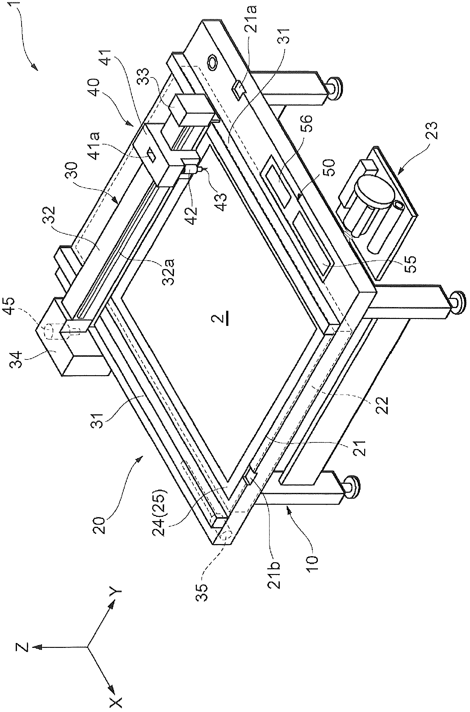
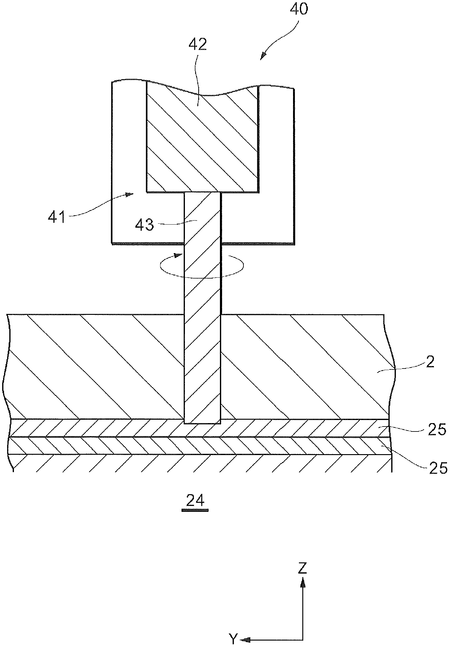
[0024] Next, preferred embodiments of the present invention will be described with reference to the drawings. As an example of a plotter (cutting device) to which the present invention is applied, figure 1 Indicates that a sheet-shaped medium to be processed is fixed and held on a processing table made of raw materials such as an acrylic plate, an aluminum composite plate, etc., and the end mill is brought into contact with the medium to be processed and raised and lowered relative to the medium to be processed, and A schematic structure of an X-Y plotter type cutting plotter 1 that moves in two orthogonal axis directions in a horizontal plane to cut a workpiece into a desired shape. In the description below, the figure 1 The upper direction in the paper is taken as the positive direction of the Z axis, figure 1 The lower right direction on the paper (the direction parallel to the Y rod 32 described later) is taken as the positive direction of the Y axis, figure 1 The l...


PUM

PropertyMeasurementUnit
thicknessaaaaaaaaaa

Abstract

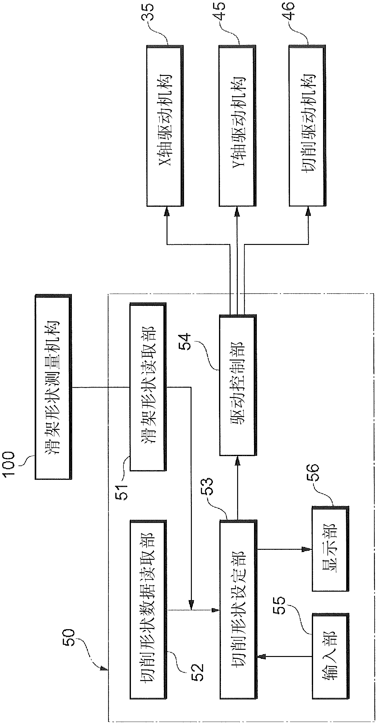
Disclosed is a cutting plotter that, even if warpage occurs in a guide rail or the like that movably supports a carriage, can prevent loss of cutting quality due to said warpage. The cutting plotter is provided with: a work table that supports a sheet-shaped medium that is being worked; an end mill that is provided above the medium supported by the work table and that cuts said medium; guide rails (31), a Y-bar (32), and a cutting drive mechanism that are provided above the work table and that support the end mill such that the end mill can move forward and backward, left and right, and up and down; and a control unit (50) that moves the end mill forward and backward, left and right, and up and down, and controls the end mill so as to cut the medium that is being worked. The cutting plotter is also provided with a carriage shape measurement mechanism (100) that detects warpage in the guide rails (31) and the Y-bar (32). The movements of the work tool are corrected on the basis of the detected warpage of the guide rails (31) and Y-bar (32).

Description

technical field [0001] The present invention relates to a cutting and plotting machine including a processing table, a processing tool supporting part, and an end mill; wherein, the above-mentioned processing table has a supporting surface for supporting a sheet-shaped medium to be processed; the above-mentioned processing tool supporting part consists of The first guide rail provided on the processing table, the second guide rail supported in a manner capable of moving along the first guide rail, and the slide frame supported in a manner capable of moving along the second guide rail; the above-mentioned processing tools are mounted on The above-mentioned carriage is used for cutting the processed medium into a desired shape. Background technique [0002] As a medium processing device that performs desired processing on a sheet-shaped to-be-processed medium, there are printer devices, cutters, and the like. As is well known, these medium processing devices place and maintai...

Claims


Application Information

Patent Timeline
Patent Type & Authority Applications(China)
IPC IPC(8): B23Q17/00B23C1/06B23Q15/18B23Q15/24B25J9/02G05B19/404
CPCB23Q15/18B23C1/06B26D2007/2678B23C1/007B26F1/3813G05B19/404G05B2219/50173G05B2219/49189B23Q17/2233B23Q15/00G05B2219/45038G05B2219/41139Y10T409/307224Y10T409/308008Y10T409/307728Y10T409/309744Y10T83/141B23Q17/00B23Q15/24
Inventor 冈部正文
Owner MIMAKI ENG
Learn More