
Lead bending device

A wire and adjusting device technology, applied in electrical components, inductance/transformer/magnet manufacturing, circuits, etc., can solve the problems of difficulty in controlling the bending angle, affecting the performance of the transformer, time-consuming and laborious, etc. Save time and effort to improve and ensure the effect of product quality

Inactive Publication Date: 2012-06-20
STATE GRID SHANDONG CHANGYI POWER SUPPLY
View PDF0 Cites 1 Cited by
  • Summary
  • Abstract
  • Description
  • Claims
  • Application Information

AI Technical Summary

Problems solved by technology

[0002] At present, in the field of transformer production, in the production of transformers below 160KVA, the low-voltage wires are all led out from the original wire of the coil, and most of them are connected in parallel. There are many kinds of cross sections, generally a rectangle with a thickness of less than 4mm and a width of more than 10mm. If you use the traditional method to bend manually, it is too difficult, and the bending angle is not easy to control, and you can only bend one piece at a time. After bending, the wire It is easy to deform and requires additional trimming, which is time-consuming and laborious, and the work efficiency is low, and it is easy to cause damage to the wire and affect the performance of the transformer

Method used


Image

  • Lead bending device
  • Lead bending device
  • Lead bending device

Examples


Embodiment Construction

[0021] Below in conjunction with accompanying drawing and embodiment, further elaborate the present invention. In the following detailed description, certain exemplary embodiments of the invention are described by way of illustration only. Needless to say, those skilled in the art would realize that the described embodiments can be modified in various different ways, all without departing from the spirit and scope of the present invention. Accordingly, the drawings and description are illustrative in nature and not intended to limit the scope of the claims.

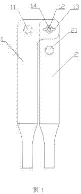
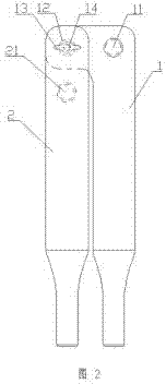
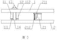
[0022] Such as figure 1 and figure 2 As shown, a wire bending device includes two bending arms, and a bending area for constraining the wire in a plane is arranged between the two bending arms. A main shaft and two pushing spools are arranged in the bending area, The wire-pushing shaft is located on the same side of the main shaft, and the two wire-pushing shafts are respectively located on both sides of the vertical...


PUM


Abstract

The invention discloses a lead bending device, which comprises two bending arms. A bending area for restraining a lead in a plane is arranged between the two bending arms and provided with a spindle and two lead pushing shafts, the two pushing shafts are arranged on the same side of the spindle and respectively located on two sides of a vertical line of a connecting line between the two lead pushing shafts, at least one lead pushing shaft rotates with the spindle as the center. The lead bending device can process leads with different sections, the bending angle is easy to control, lead bending quality is high, and time and labor are saved.

Description

technical field [0001] The invention relates to a tool for bending wires, in particular to a wire bending device. Background technique [0002] At present, in the field of transformer production, in the production of transformers below 160KVA, the low-voltage wires are all led out from the original wire of the coil, and most of them are connected in parallel. There are many kinds of cross sections, generally a rectangle with a thickness of less than 4mm and a width of more than 10mm. If you use the traditional method to bend manually, it is too difficult, and the bending angle is not easy to control, and you can only bend one piece at a time. After bending, the wire It is easy to deform and requires additional trimming, which is time-consuming and laborious, and the work efficiency is low, and it is easy to cause damage to the wires and affect the performance of the transformer. Contents of the invention [0003] The technical problem to be solved by the present invention...

Claims


Application Information

Patent Timeline
Patent Type & Authority Applications(China)
IPC IPC(8): B21F1/00H01F41/00
Inventor 杨曰明张增光张勇曲金波孟令强董峰李金玲
Owner STATE GRID SHANDONG CHANGYI POWER SUPPLY
Learn More