Check patentability & draft patents in minutes with Patsnap Eureka AI!

Double-cavity hydraulically coupled anti-flying device

A cavity fluid, anti-flying technology, applied in the field of hydraulic components, can solve problems such as accidents

Active Publication Date: 2014-04-02
GUANGDONG ZHONGXING POWER TRANSMISSION
View PDF6 Cites 0 Cited by
  • Summary
  • Abstract
  • Description
  • Claims
  • Application Information

AI Technical Summary

Problems solved by technology

[0002] At present, with the advancement of science and technology and the need to adapt to economic development, the working water pressure and energy of small and medium-sized hydroelectric generating units are getting higher and higher, and the safety protection requirements for working equipment are getting higher and higher. If small and medium-sized hydroelectric generating units Or the rotation speed of large inertia equipment exceeds the allowable speed value, which will definitely cause accidents

Method used


Image

  • Double-cavity hydraulically coupled anti-flying device
  • Double-cavity hydraulically coupled anti-flying device
  • Double-cavity hydraulically coupled anti-flying device

Examples


Embodiment 1

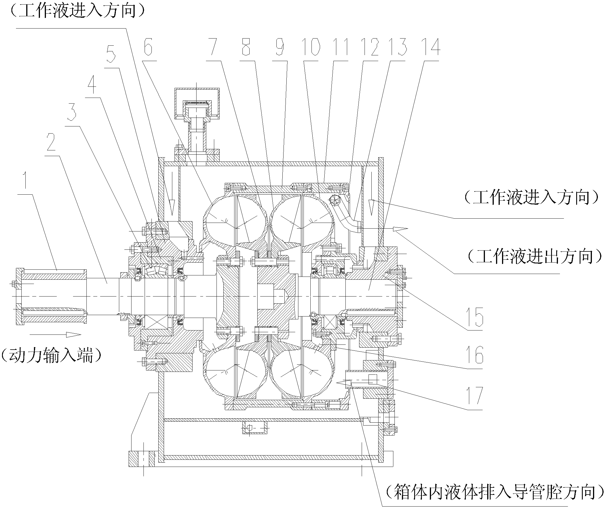
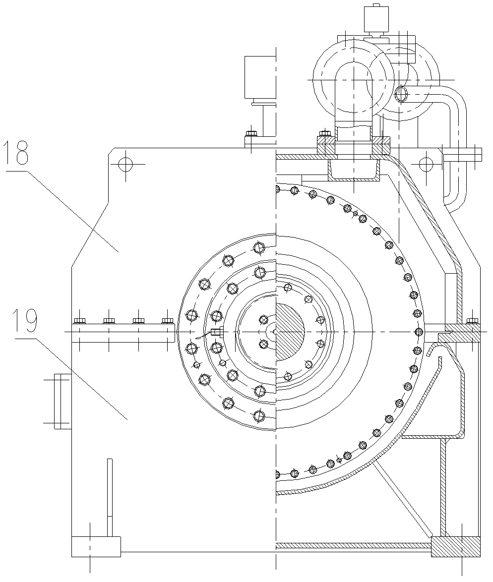
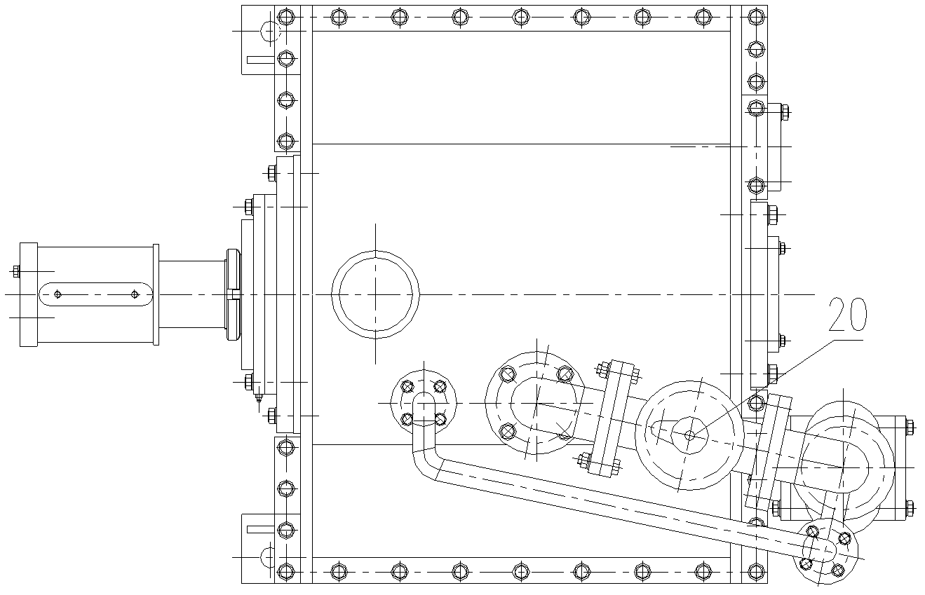
[0018] Such as figure 1 , 2 , 3, 4, and 5, the double-cavity hydraulic coupling anti-flyaway device of the present invention includes a casing 25, a rotating assembly, and a liquid supply system.

[0019] The box body 25 is composed of a box seat 19 and a box cover 18, and the box body 25 supports the entire liquid supply system;

[0020] The rotating assembly includes an input assembly and an output assembly;

[0021] The input components mainly include: input shaft 2, pump wheel A, pump wheel B, pump wheel connection cylinder 9, casing connection cylinder 11 and casing, etc.;

[0022] The output components mainly include: turbine A, turbine B, output shaft 14, etc.;

[0023] Such as Figure 5 As shown, the pulley sleeve 1 on the input shaft 2 of the input assembly is connected to the working machine 23 through a transmission mechanism 24, and the output assembly is fixedly connected to the box body 25; the transmission mechanism 24 shown is a belt transmission structure...


PUM


Abstract

The invention discloses a double-cavity hydraulically coupled anti-flying device, which comprises a working machine, a box body consisting of a box seat and a box cover, a rotating component supported by the box body and a liquid supply system, wherein the rotating component comprises an input component which is connected with the working machine in a transmission manner, and comprises two pump wheels, and an output component which is fixed on the box body, and comprises two worm wheels; the input component comprises an input shaft, a pump wheel A, a pump wheel B, a pump wheel connection drum and a shell connection drum; the output component comprises a worm wheel A, a worm wheel B and an output shaft; two uniform working cavities are formed by connecting the pump wheel A and the worm wheel A as well as the pump wheel B and the worm wheel B; and the liquid supply system is fixedly connected to the box body. By the double-cavity hydraulically coupled anti-flying device, the rotating speed of the working machine can be reduced, so that an effect of anti-flying is achieved; the double-cavity hydraulically coupled anti-flying device is particularly suitable for anti-flying devices, of which the working machines have the input rotating speed of between 500 and 3,000 r / min and the power range of between 150 and 20,000 KW, or other sets of equipment which requires high speed braking.

Description

Technical field: [0001] The invention relates to the field of hydraulic components, in particular to an anti-flyaway device used for small and medium hydroelectric generator sets or other equipment with large inertia and need to limit the rotational speed. Background technique: [0002] At present, with the advancement of science and technology and the need to adapt to economic development, the working water pressure and energy of small and medium-sized hydroelectric generating units are getting higher and higher, and the safety protection requirements for working equipment are getting higher and higher. If small and medium-sized hydroelectric generating units Or if the speed of the large inertia equipment exceeds the allowable speed value, it will definitely cause an accident. Invention content: [0003] The purpose of the present invention is to provide a double-cavity hydraulic coupling anti-flyaway device, which uses liquid as the working medium, and the hydraulic elem...

Claims


Application Information

Patent Timeline
Patent Type & Authority Patents(China)
IPC IPC(8): F03B15/18
CPCY02E10/226Y02E10/20
Inventor 刘建强谢福志黄金火黄达机
Owner GUANGDONG ZHONGXING POWER TRANSMISSION
Features
  • R&D
  • Intellectual Property
  • Life Sciences
  • Materials
  • Tech Scout
  • Unparalleled Data Quality
  • Higher Quality Content
  • 60% Fewer Hallucinations
Learn More