Vehicle gear selection mechanism and automobile

A technology for shifting gears and vehicles, which is applied in the direction of mechanical equipment, engine components, and engine lubrication. It can solve the problems of easy air-drying loss, insufficient lubrication, and waste of lubricating grease, so as to improve NVH performance and avoid parts wear. , The effect of reducing maintenance costs

Active Publication Date: 2015-09-23
WUHU WANLIYANG TRANSMISSION CO LTD
View PDF5 Cites 0 Cited by
  • Summary
  • Abstract
  • Description
  • Claims
  • Application Information

AI Technical Summary

Problems solved by technology

In actual operation, grease is usually applied on the outer surface of the ball head body 12 or the inner wall surface of the ball head sheath 13 for lubrication, but since there is no continuous oil supply structure to supply grease to the two, the ball head body and The amount of lubricating grease between the ball bushes is limited, so it is often necessary to add, and the adding method of lubricating grease is currently manually added, which brings a lot of trouble to the use of the shift mechanism
When adding lubricating grease, due to manually applying lubricating grease on the outer surface of the ball head body 12 or the inner wall surface of the ball head sheath 13, the coating thickness of the lubricating grease will inevitably be uneven. During use, For lubricating grease with a large coating thickness, due to the rotation of the ball head body 12, a part of the excess lubricating grease remaining on the inner wall surface of the ball head sheath 13 is prone to air-drying loss because it does not contact the ball head body 12 , resulting in unnecessary waste
In addition, due to the uneven coating thickness of the lubricating grease, as the number of shifts increases, there will be a part of the area between the ball head body 12 and the ball head sheath 13 that is less thickly coated with lubricating grease, resulting in a lack of lubricating grease in the ball head. The lubrication between the body 12 and the ball head sheath 13 is insufficient, and the lubricating grease is air-dried in the air. After a long time of use, there will be abnormal noises between the ball head body 12 and the ball head sheath 13, and the gear will be shifted. Astringency and other problems

Method used


Image

  • Vehicle gear selection mechanism and automobile
  • Vehicle gear selection mechanism and automobile
  • Vehicle gear selection mechanism and automobile

Examples


Embodiment 1

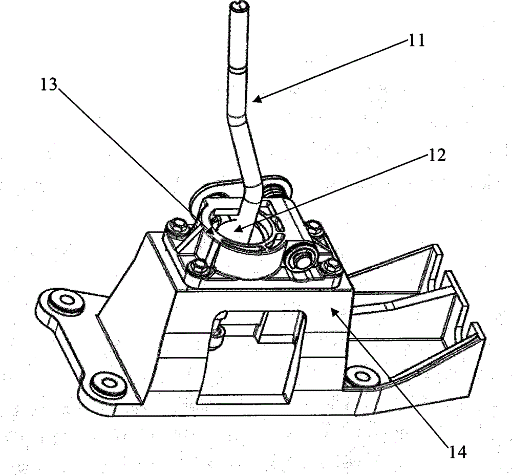
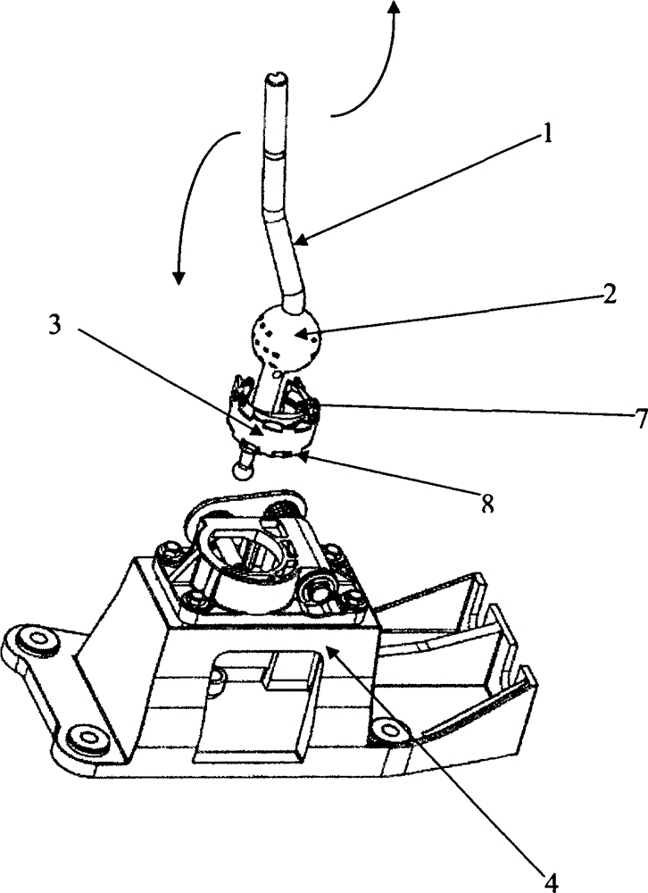
[0033] Such as figure 2 As shown, in this embodiment, the vehicle gear selection mechanism includes a base 4, a gear selection lever 1, a ball head sheath 3 with a spherical inner cavity, a ball head body 2, and an oil storage unit. Wherein, the ball head sheath 3 is arranged on the base 4 , the ball head body 2 is arranged at one end of the shift lever 1 , and the ball head body 2 is embedded in the spherical inner cavity of the ball head sheath 3 . The movement of the shift lever 1 drives the ball body 2 to rotate in the spherical inner cavity of the ball sheath 3 .

[0034] In this example, if Figure 5 As shown, the ball head sheath 3 includes a sheath upper part 7 and a sheath lower part 8, and the sheath upper part 7 and the sheath lower part 8 are detachably connected together to form a spherical inner cavity together, and the ball head body 2 is embedded in the in the spherical cavity.

[0035] Lubricating grease is stored in the oil storage unit, and the oil stora...

Embodiment 2

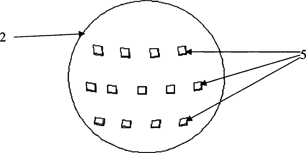
[0048] The difference between this embodiment and Embodiment 1 is that: in this embodiment, the oil storage unit includes a first groove 5 provided on the ball head body 2, and lubricating grease is arranged in the first groove 5 . That is to say, the oil storage unit does not have the second groove 6 provided on the ball head sheath 3 .

[0049] Other structures in this embodiment are the same as those in Embodiment 1, and will not be repeated here.

[0050] In this embodiment, only the first groove 5 is provided on the ball head body 2, and the ball head sheath 3 is not provided with a groove. In close contact, when the lubricating grease in the first groove 5 lubricates itself, a part of the lubricating grease will adhere to the ball sheath 3 and play the role of lubricating the ball sheath 3 at the same time. However, the ball head sheath 3 is only lubricated by the lubricating grease in the first groove 5, lacks its own lubrication, let alone lubricates the ball body 2, ...

Embodiment 3

[0052] The difference between this embodiment and Embodiment 1 is that in this embodiment, the oil storage unit includes a second groove 6 opened on the ball head sheath 3, and the second groove 6 is provided with lubricating grease . That is, the oil storage unit does not have the first groove 5 provided on the spherical body 2 .

[0053] Other structures in this embodiment are the same as those in Embodiment 1, and will not be repeated here.

[0054] In this embodiment, since only the second groove 6 is set on the ball head sheath 3, no groove is set on the ball head body 2. When the lubricating grease in the second groove 6 lubricates itself, a part of the lubricating grease will adhere to the ball body 2 and play the role of lubricating the ball body 2 at the same time. However, if the ball body 2 is only lubricated by the lubricating grease in the second groove 6, and lacks its own lubrication, let alone lubricate the ball sheath 3, its effect is not as good as that of ...


PUM


Abstract

The invention provides an automobile gear selecting and shifting mechanism, which comprises a gear selecting and shifting lever, a bulb protecting sleeve, a bulb and an oil storage unit, wherein the bulb can be embedded into the bulb protecting sleeve, is arranged at one end of the gear selecting and shifting lever and is driven to rotate in the bulb protecting sleeve by means of movement of the gear selecting and shifting lever. Lubricating greases are stored in the oil storage unit and can enter the space between the outer surface of the bulb and the inner wall surface of the bulb protecting sleeve. The automobile gear selecting and shifting mechanism solves the problem that an automobile gear selecting and shifting mechanism in the prior art needs to be frequently added with lubricating greases, and avoids abrasion of parts caused by decrease of the lubricating greases.

Description

technical field [0001] The invention belongs to the technical field of automobile manufacturing, and in particular relates to a vehicle gear selection mechanism and an automobile with the vehicle gear selection mechanism. Background technique [0002] The working principle of the automobile transmission is to expand the range of driving force and speed of the automobile by changing the transmission ratio to meet different driving conditions. With the continuous development of automobile technology, the requirements for the shifting quality of the transmission are getting higher and higher. [0003] At present, the general-purpose vehicle gear selection mechanism in automobiles generally smears lubricating grease between the ball head body and the ball head sheath connected with the gear selection lever during its work, and the ball head body and the ball head sheath are oiled by the lubricating grease. Lubricate when there is relative movement between them, so as to improve ...

Claims


Application Information

Patent Timeline
Patent Type & Authority Patents(China)
IPC IPC(8): F16H59/02F16N1/00
Inventor 刘翔鲍勇仲张玉民马威康军波
Owner WUHU WANLIYANG TRANSMISSION CO LTD
Why Eureka
Try Eureka