
Rotary speed reducer, assembling method and engineering machinery

A technology of slewing reducer and planetary deceleration, which is applied in the direction of mechanical equipment, transmission parts, gear lubrication/cooling, etc. It can solve the problems of complex heavy-duty working conditions and other problems, and achieve the effect of avoiding easy pollution and ensuring the lubrication state

Pending Publication Date: 2022-08-02
XUZHOU XCMG MINING MACHINERY CO LTD
View PDF0 Cites 0 Cited by
  • Summary
  • Abstract
  • Description
  • Claims
  • Application Information

AI Technical Summary

Problems solved by technology

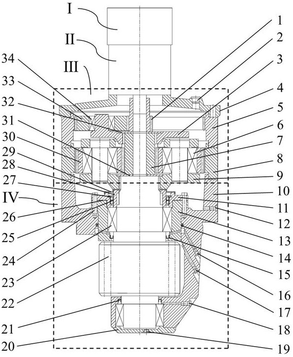
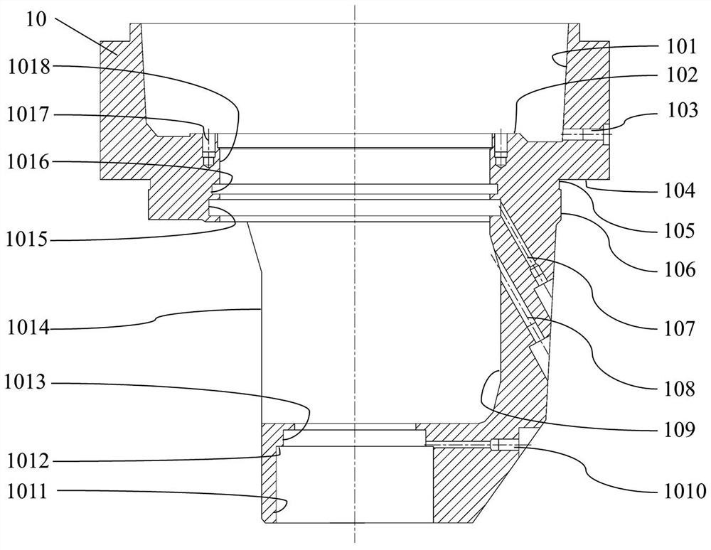
[0003] In view of the above problems, the present invention proposes a rotary reducer, the power output gear is supported at both ends, and the structural strength and rigidity are far superior to the traditional cantilever support; the power output part is completely isolated from the oil chamber of the planetary reduction part, and can be filled Lubricants of different media can meet the requirements of complex and heavy-duty working conditions; the output rotary gear of the reducer and the slewing support form a grease tank, which replaces the open lubrication pool, avoiding the problem that the reserved grease is easily polluted, and realizes the Lubrication with new grease ensures the lubrication state of the rotary meshing gear pair

Method used


Image

  • Rotary speed reducer, assembling method and engineering machinery
  • Rotary speed reducer, assembling method and engineering machinery
  • Rotary speed reducer, assembling method and engineering machinery

Examples


Embodiment Construction

[0047] In order to make the purposes, technical solutions and advantages of the embodiments of the present invention clearer, the technical solutions in the embodiments will be described clearly and completely below with reference to the accompanying drawings in the embodiments of the present invention, and the following embodiments are used to illustrate the present invention , but are not intended to limit the scope of the present invention.

[0048] In the description of the present invention, it should be noted that the terms "upper", "lower", "front", "rear", "left", "right", "vertical", "inner", "outer", etc. The indicated orientation or positional relationship is based on the orientation or positional relationship shown in the accompanying drawings, which is only for the convenience of describing the present invention and simplifying the description, rather than indicating or implying that the indicated device or element must have a specific orientation or a specific ori...


PUM


Abstract

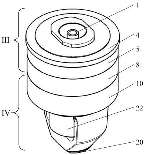
The invention discloses a rotary speed reducer, an assembling method and engineering machinery. The rotary speed reducer comprises a braking assembly, a driving assembly, a two-stage planetary speed reduction assembly and a power output assembly which are arranged in sequence. One end of an output shaft of the driving assembly is connected with the braking assembly, and the other end is connected with a first-stage sun gear of the two-stage planetary reduction assembly; a gear shaft of the power output assembly is connected with a second-stage planet carrier of the two-stage planet speed reduction assembly through a spline pair. Oil cavities of the two-stage planetary speed reduction assembly and the power output assembly are completely isolated, and lubricating agents of different media can be filled. The power output gear is supported at the two ends, and the structural strength and rigidity are far better than those of traditional cantilever type supporting; bearings of the power output assembly are lubricated by lubricating grease, and low-speed heavy-load working condition requirements can be met; the output rotary teeth of the speed reducer and the rotary support form the lubricating grease groove, an open type lubricating pool is replaced, the problem that stored lubricating grease is prone to being polluted is solved, and the lubricating state of the rotary meshing gear pair is guaranteed.

Description

technical field [0001] The invention belongs to the technical field of construction machinery reducers, in particular to a rotary reducer. Background technique [0002] At present, most of the rotary reducers of heavy construction machinery widely used in the world use hydraulic motors to drive external two-stage or three-stage planetary reducers, and the output gears of the reducers in the prior art are mostly cantilever supports, and the bearings are It has large force and low service life, and often requires a large developed lubrication pool. There are problems that the reserved grease is easily contaminated and the lubrication state of the rotating meshing gear pair cannot be effectively guaranteed. SUMMARY OF THE INVENTION [0003] In view of the above problems, the present invention proposes a rotary reducer, the power output gear is supported at both ends, and its structural strength and rigidity are far superior to the traditional cantilever support; the power out...

Claims


Application Information

Patent Timeline
Patent Type & Authority Applications(China)
IPC IPC(8): F16H57/021F16H57/023F16H57/04F16H57/029
CPCF16H57/023F16H57/021F16H57/0424F16H57/045F16H57/029F16H57/0471F16H57/0479F16H57/0482
Inventor 王勇渠立红杨裕丰王春磊石立京刘永参付桂山汪允显文俊张聪聪张志洋
Owner XUZHOU XCMG MINING MACHINERY CO LTD
Learn More