Backlight module and display device adopting the backlight module

A technology for a backlight module and a display device, applied in the field of surface light sources, can solve the problems of high material cost, disadvantageous narrow frame and light weight, and many materials, and achieve the effect of reducing weight and material cost.

Inactive Publication Date: 2012-06-20
AU OPTRONICS CORP
View PDF4 Cites 11 Cited by
  • Summary
  • Abstract
  • Description
  • Claims
  • Application Information

AI Technical Summary

Problems solved by technology

[0003] In the existing liquid crystal display device 100, the plastic frame 113 extends from the inside of the back plate 111 to the outside of the back plate 111, resulting in a wider width D1 of the cover portion 131 of the front frame 130 of the liquid crystal display device 100.
However, current display devices all pursue narrow borders (that is, the width D1 needs to be reduced as much as possible),

Method used


Image

  • Backlight module and display device adopting the backlight module
  • Backlight module and display device adopting the backlight module
  • Backlight module and display device adopting the backlight module

Examples


Embodiment Construction

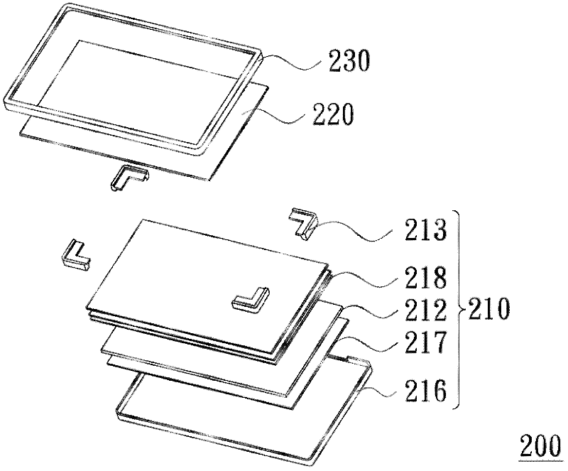
[0071] image 3 It is an exploded perspective view of a display device according to an embodiment of the present invention. Figure 4 for image 3 A partial three-dimensional cross-sectional schematic diagram of the display device shown. Figure 5 for image 3 A three-dimensional schematic view of the support of the display device shown. see Figure 3 to Figure 5, the display device 200 of this embodiment includes a backlight module 210 and a display panel 220 . The backlight module 210 includes an optical component 212 and a plurality of support members 213 . These supporting pieces 213 are disposed on the edge of the optical member 212 . Each supporting member 213 has a side wall 214 and a supporting portion 215 , the side wall 214 is located beside the edge of the optical component 212 , and the supporting portion 215 extends from the side wall 214 to the top of the optical component 212 . The side wall 214 has a first portion 214a located below the support portion 2...


PUM


Abstract

The invention discloses a backlight module and a display device adopting the backlight module. The backlight module includes an optical component and a plurality of support parts. The support parts are arranged on the periphery of the optical component. Each of the support parts is provided with a side wall and a support part. The side wall is arranged on the periphery of the optical component. The support part extends to the above of the optical component from the side wall. The side wall is provided with a first part below the support part and a second part above the support part. The invention also provides the display device adopting the backlight module. The backlight module and the display device have small weights and small thicknesses.

Description

technical field [0001] The invention relates to a surface light source, and in particular to a backlight module and a display device using the backlight module. Background technique [0002] figure 1 is a three-dimensional exploded schematic diagram of an existing liquid crystal display device, and figure 2 yes figure 1 A partial cross-sectional schematic diagram of a liquid crystal display device. see figure 1 and figure 2 , the conventional liquid crystal display device 100 includes a backlight module 110 , a liquid crystal display panel 120 and a front frame 130 . The backlight module 110 includes a backplane 111 , a light guide plate 112 , a plastic frame 113 and a plurality of optical films 117 . The light guide plate 112 is disposed on the back plate 111 , and the optical film 117 is disposed on the light guide plate 112 . The plastic frame 113 has a groove 114 and a bearing portion 115 . The sidewall 116 of the back plate 111 protrudes into the groove 114 , ...

Claims


Application Information

Patent Timeline
IPC IPC(8): F21S8/00F21V17/10G02F1/13357
Inventor 刘文贵陈圣文洪裕民
Owner AU OPTRONICS CORP
Why Eureka
Try Eureka