Supercharge Your Innovation With Domain-Expert AI Agents!

Detection circuit for output laser energy of laser welding machine

A laser welding machine and detection circuit technology, applied in the field of detection circuits, can solve the problems of measurement accuracy and consistency deviation, inconvenient debugging and modification, application environment temperature influence, etc., and achieves low design cost, strong versatility, strong The effect of product competitiveness

Active Publication Date: 2014-01-08
WUHAN HGLASER ENG CO LTD
View PDF5 Cites 0 Cited by
  • Summary
  • Abstract
  • Description
  • Claims
  • Application Information

AI Technical Summary

Problems solved by technology

[0002] At present, the widely used laser welding machines at home and abroad are mainly optical fiber conduction welding machines. In the environment of actively promoting energy saving and emission reduction and strengthening low-carbon industrial production, laser equipment also urgently needs to improve the stability of its energy output. Therefore, it is necessary to The energy output of laser equipment is detected. At present, most of the detection of output laser energy in laser equipment products adopts a simple design structure of a first-level operational amplifier detection plus a first-level operational amplifier isolation amplifier circuit. Such a structure lacks sufficient attention to the detection environment. And there are some defects in the details of the actual application. In the actual application, the difference in the operation and installation of the existing circuit causes the measurement accuracy and consistency deviation, which is greatly affected by the application environment temperature and inconvenient to change the actual debugging. question

Method used


Image

  • Detection circuit for output laser energy of laser welding machine
  • Detection circuit for output laser energy of laser welding machine
  • Detection circuit for output laser energy of laser welding machine

Examples


Embodiment Construction

[0021] In order to facilitate a further understanding of the structure and achieved effects of the present invention, preferred embodiments are described in detail below in conjunction with the accompanying drawings.

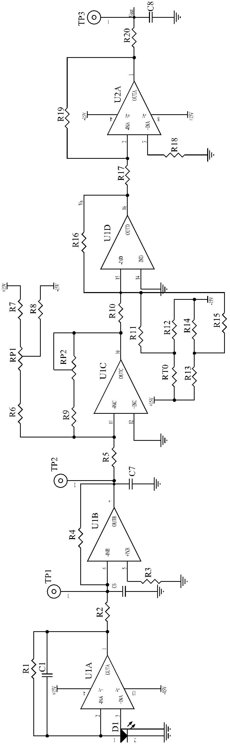
[0022] Such as figure 1 As shown, a laser welding machine output laser energy detection circuit of the present invention includes a diode primary detection circuit, an inverter circuit, a system zero adjustment and signal amplification circuit, and a temperature compensation and isolation output circuit that are electrically connected in sequence.

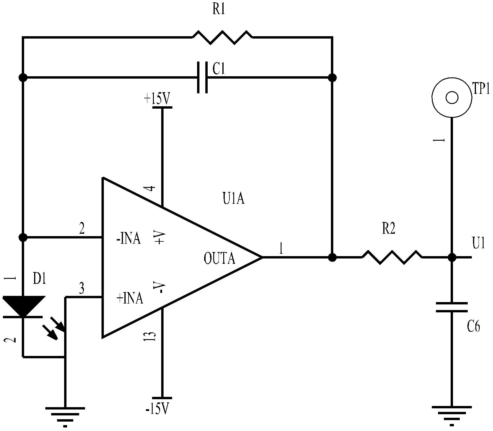
[0023] Such as figure 2 As shown, the photodiode primary detection circuit is a first-stage circuit, which serves as a sampling circuit to realize the functions of converting laser power into a current signal and converting a current signal into a voltage signal. The photodiode primary detection circuit among the present invention is made up of photodiode D1, feedback resistor R1, feedback capacitor C1, capacitor C...


PUM


Abstract

The invention discloses a detection circuit for the output laser energy of a laser welding machine. The detection circuit comprises a diode primary detecting circuit, a phase inverting circuit, a system zero-setting and signal amplification circuit and a temperature compensation and isolation output circuit, which are electrically connected in sequence; the photodiode primary detecting circuit serves as a sampling circuit to realize the functions of converting laser power into a current signal and converting the current signal into a voltage signal; the phase inverting circuit realizes the function of a phase invertor and provides a presignal for the system zero-setting and signal amplification circuit; the system zero-setting and signal amplification circuit realizes the functions of system zero setting and signal amplifying; and the temperature compensation and isolation output circuit performs the functions of temperature compensation and isolation output. The detection circuit has the advantages of strong popularity, operation flexibility, stronger anti-interference characteristic, relatively low design cost, high efficiency, energy saving and strong product competitiveness and the system laser energy detection precision is improved.

Description

technical field [0001] The invention relates to a detection circuit, in particular to a detection circuit for outputting laser energy of a laser welding machine adopting an energy feedback control mode. Background technique [0002] At present, the widely used laser welding machines at home and abroad are mainly optical fiber conduction welding machines. In the environment of actively promoting energy saving and emission reduction and strengthening low-carbon industrial production, laser equipment also urgently needs to improve the stability of its energy output. Therefore, it is necessary to The energy output of laser equipment is detected. At present, most of the detection of output laser energy in laser equipment products adopts a simple design structure of a first-level operational amplifier detection plus a first-level operational amplifier isolation amplifier circuit. Such a structure lacks sufficient attention to the detection environment. And there are some defects i...

Claims


Application Information

Patent Timeline
Patent Type & Authority Patents(China)
IPC IPC(8): G01J1/44G01J1/02
Inventor 卢飞星孙林波叶姣
Owner WUHAN HGLASER ENG CO LTD
Features
  • R&D
  • Intellectual Property
  • Life Sciences
  • Materials
  • Tech Scout
  • Unparalleled Data Quality
  • Higher Quality Content
  • 60% Fewer Hallucinations
Learn More