Remote control cursor positioning method and device, remote control and cursor positioning system
A technology for cursor positioning and remote control, which is applied to the input/output process of instruments, electrical digital data processing, and data processing, and can solve problems such as remote control cursor positioning deviation.
- Summary
- Abstract
- Description
- Claims
- Application Information
AI Technical Summary
Problems solved by technology
Method used
Image

Examples
Embodiment 1
[0071] figure 2 A flow chart of the method for locating the cursor of the remote controller provided by Embodiment 1 of the present invention is shown, and for convenience of description, only parts related to this embodiment are shown.
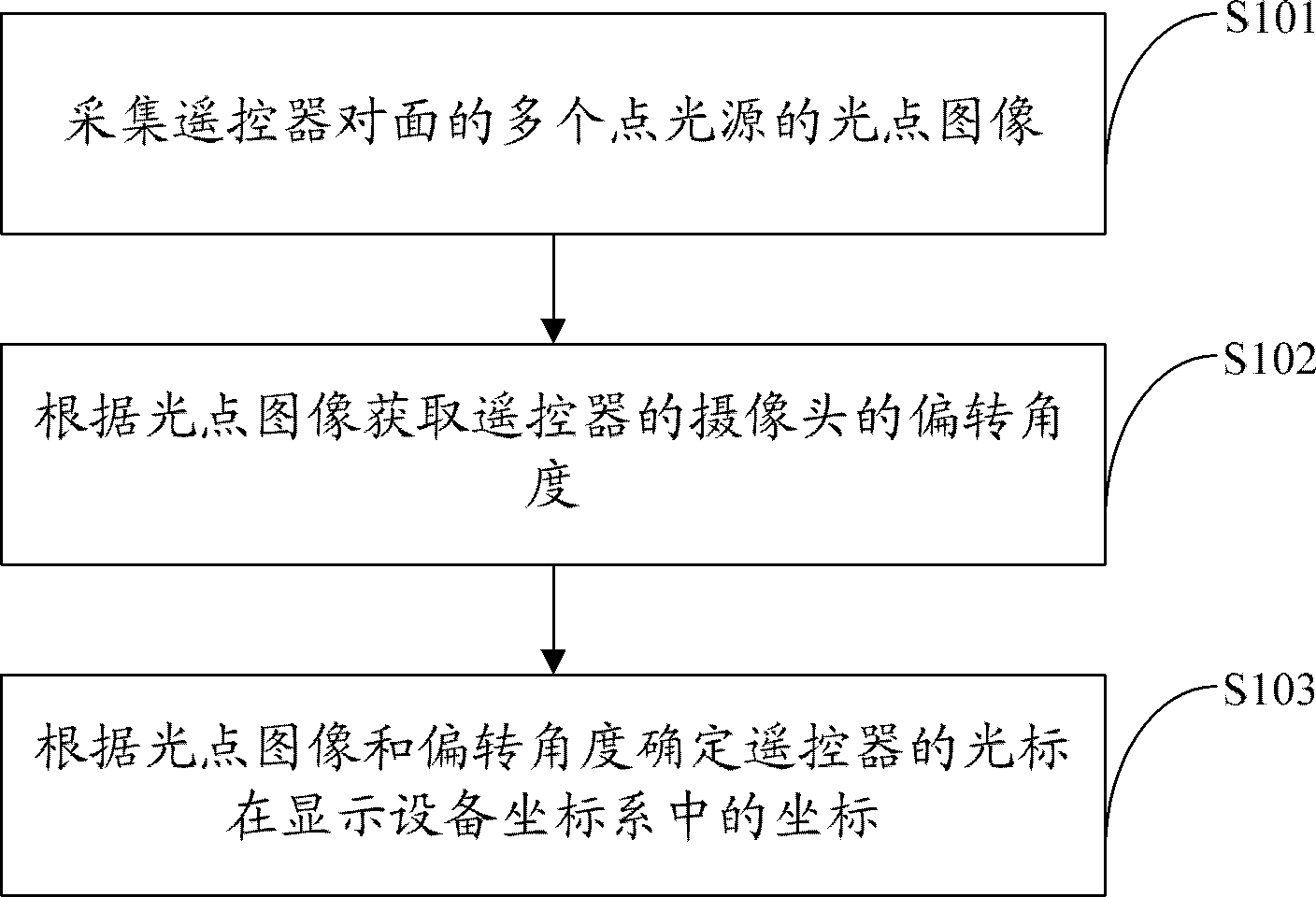
[0072] The remote control cursor positioning method is mainly realized through the following steps:
[0073] In step S101, light spot images of multiple point light sources opposite to the remote control are collected.
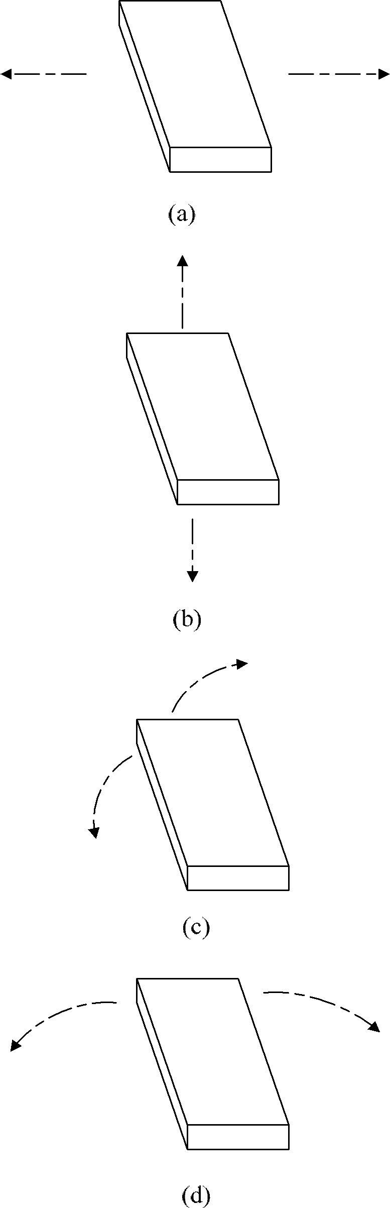
[0074] In this embodiment, the position of the point light source is usually set in the direction of the display device (it can be a TV monitor or a computer monitor, etc.), specifically, it may be set on the frame of the display, or it may be set near the display device, and its position does not have to be strict. limit so that it can be imaged by the camera on the front of the remote control. In this step, the camera carried by the remote controller captures a frame of light point images, and each image contains several...
Embodiment 2
[0084] Figure 4 A flow chart of the method for locating the cursor of the remote controller provided by Embodiment 2 of the present invention is shown, and for the convenience of description, only the parts related to this embodiment are shown.
[0085] Since the light point image collected by the camera contains noise, this embodiment gives priority to corresponding processing on the image. The remote control cursor positioning method provided by this embodiment can be mainly realized through the following steps:
[0086] In step S201, light point images of multiple point light sources opposite to the remote controller are collected.
[0087] In step S202, denoising and binarization are performed on the spot image to obtain a processed spot image.
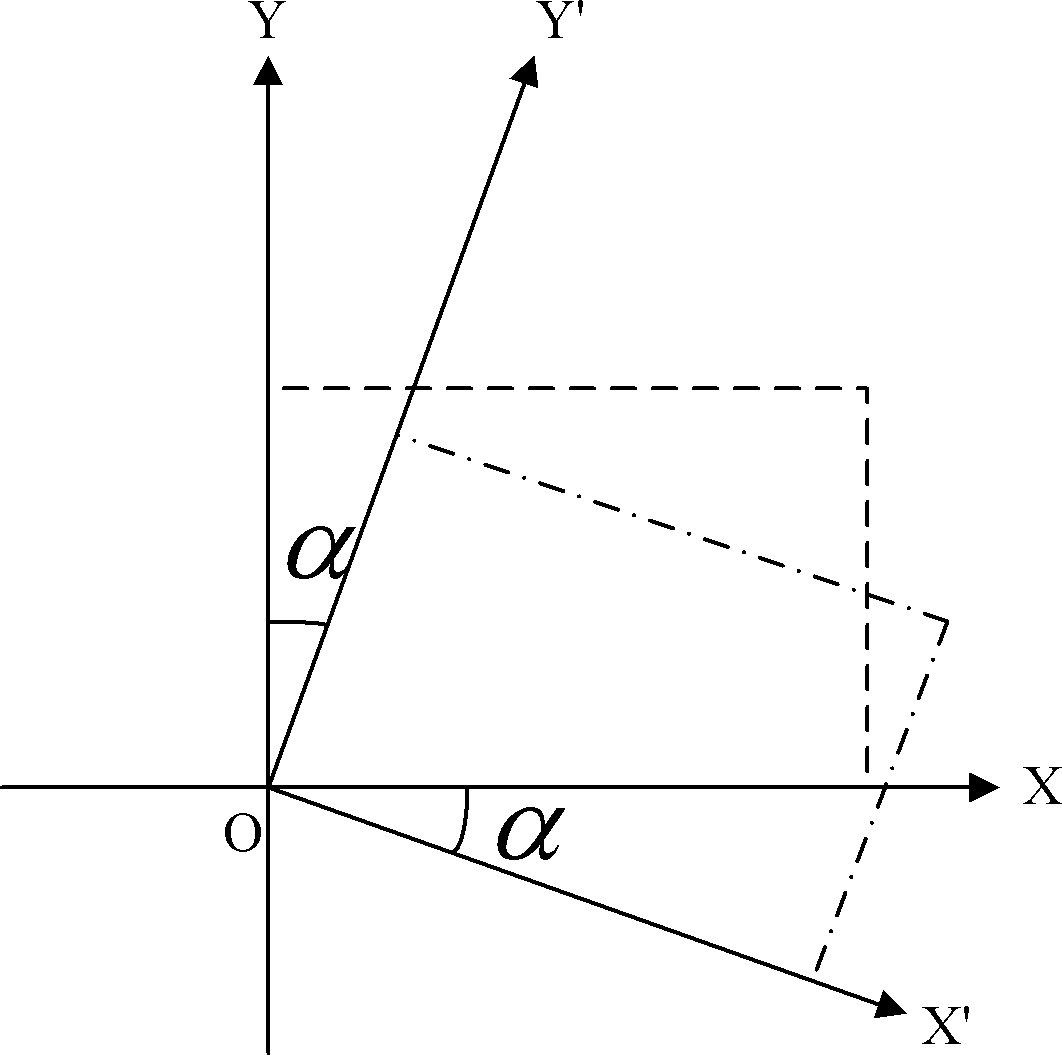
[0088] In step S203, the deflection angle of the camera of the remote controller is acquired according to the light spot image.
[0089] In step S204, the coordinates of the cursor of the remote controller in the coordinate sys...
Embodiment 3
[0094] Figure 5 A flow chart of determining the coordinates of the cursor in the display coordinate system provided by Embodiment 3 of the present invention is shown. For the convenience of description, only the parts related to this embodiment are shown.
[0095] This embodiment provides a better way to implement step S103 in the first embodiment above, and this embodiment is based on the fact that multiple point light sources are on the same straight line. Specifically, the coordinates of the cursor in the coordinate system of the display device can be determined by the following The method described above is implemented:
[0096] In step S301, determine the center of gravity of each light spot in the light spot image, and get the geometric center of the center of gravity of all light spots as the first coordinate of the cursor in the camera coordinate system;
[0097] In this embodiment, the coordinates of the center of gravity of the light spot are taken for correspondin...
PUM
 Abstract
Description
Claims
Application Information
 - Generate Ideas
- Intellectual Property
- Life Sciences
- Materials
- Tech Scout
- Unparalleled Data Quality
- Higher Quality Content
- 60% Fewer Hallucinations
Browse by: Latest US Patents, China's latest patents, Technical Efficacy Thesaurus, Application Domain, Technology Topic, Popular Technical Reports.
© 2025 PatSnap. All rights reserved.Legal|Privacy policy|Modern Slavery Act Transparency Statement|Sitemap|About US| Contact US: help@patsnap.com