TM mode dielectric filter

A dielectric filter and filter technology, applied in the field of communication, can solve problems such as inconvenience, difficulty in achieving high electrical insertion loss and high intermodulation, and inability to fully apply the temperature range of the filter application

Inactive Publication Date: 2012-06-20
MOBILE ANTENNA TECH SHENZHEN
View PDF4 Cites 33 Cited by
  • Summary
  • Abstract
  • Description
  • Claims
  • Application Information

AI Technical Summary

Benefits of technology

This patented technology describes a new design for electronic components called TE (transmitting) modes used in communication systems such as radar devices or wireless communications equipment. These filters use special materials made from specific chemicals to absorb energy when they vibrate at certain frequencies. By compressively bending these materials around them, there will be strong connections between different elements inside the device without requiring any extra steps during manufacturing process. Overall, this innovation improves performance and efficiency while maintaining reliable operation over long periods of usage.

Problems solved by technology

This patented technical problem addressed in this patents relates to improving the performance of certain types of filters called TE MTM mode dielectrofilter(TMI). Specifically, current methods involve adding extra parts like springs or bolts to connect the inductor's terminals to the housing of the device. These connections may fail under extreme temperatures without being able to maintain their effectiveness over longer periods of operation. Therefore there needs improvement in these techniques to ensure reliable functionality across various operating conditions.

Method used


Image

  • TM mode dielectric filter
  • TM mode dielectric filter
  • TM mode dielectric filter

Examples


Embodiment Construction

[0054] In order to make the object, technical solution and advantages of the present invention clearer, the present invention will be further described in detail below in conjunction with the accompanying drawings and embodiments. It should be understood that the specific embodiments described here are only used to explain the present invention, not to limit the present invention.

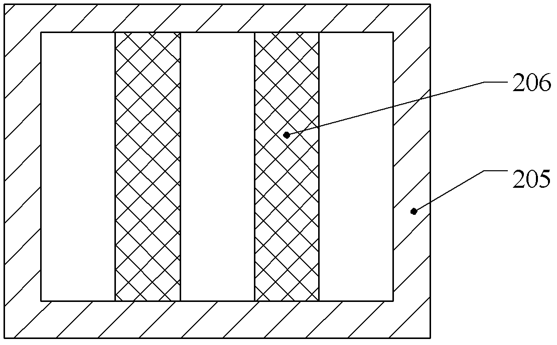
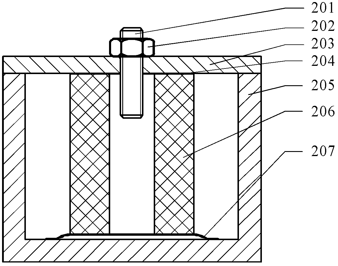
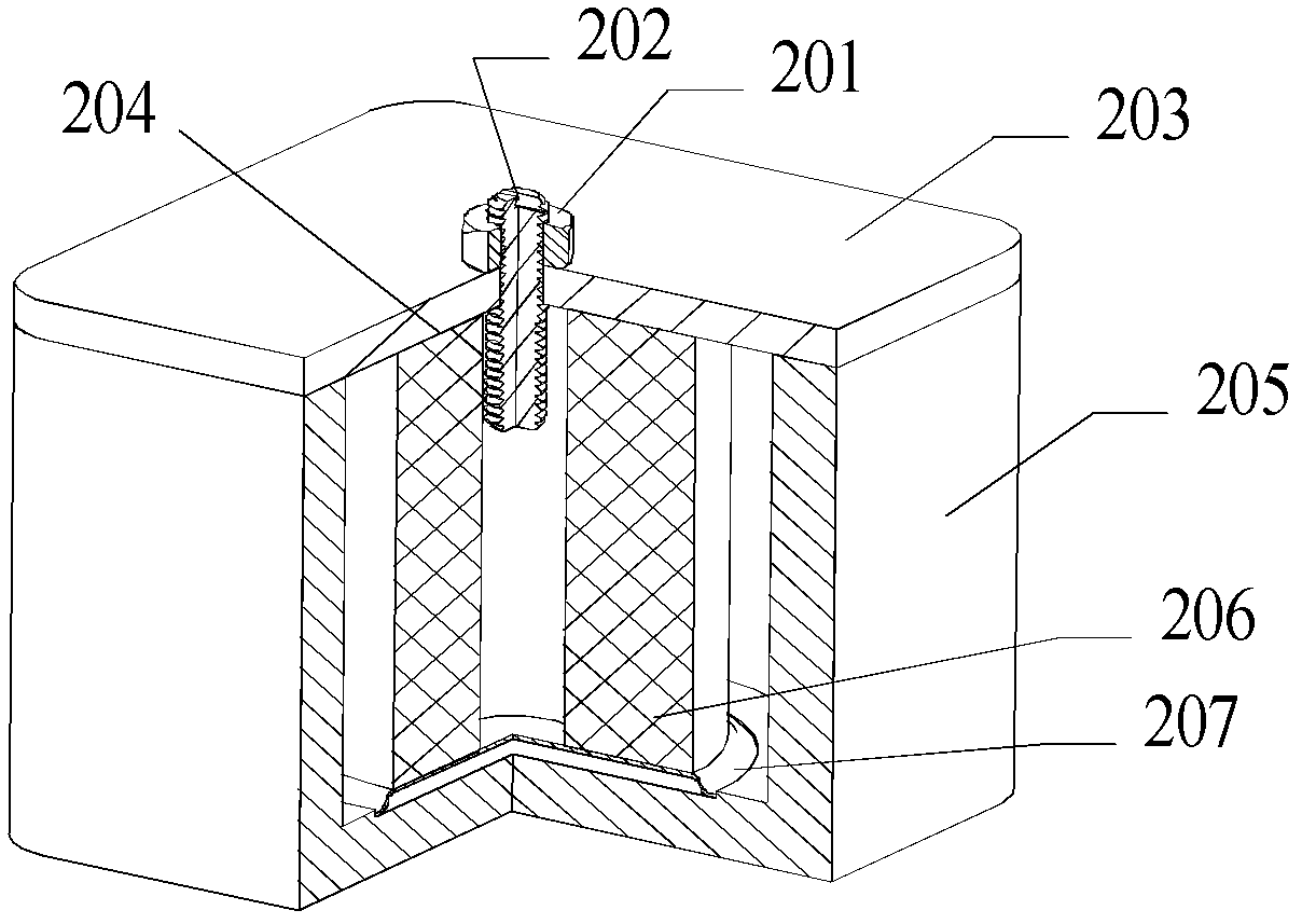
[0055] see Figure 4 ~ Figure 6 , the present invention provides a TM mode dielectric filter 100, comprising a plurality of filter units 10, each of said filter units 10 comprising:

[0056]The elastic connection mechanism 11 includes an elastic element and an upper cover 111;

[0057] The dielectric resonator 12 is arranged in the resonant cavity 13 and is in the shape of a cylinder. A hole structure 121 is opened in the cylinder; Connection at the bottom of the lumen;

[0058] The resonant cavity 13 includes one or more concave cavities 131 , and coupling windows are opened on the concave cavi...


PUM


Abstract

The invention discloses a TM (Transverse Magnetic) mode dielectric filter. The TM mode dielectric filter comprises a plurality of filter units, each of the filter units consists of an elastic connecting mechanism, a dielectric resonator and a resonance cavity, wherein the elastic connecting mechanism comprises an elastic component and an upper cover; the columnar dielectric resonator is arranged in the resonance cavity, the upper end surface of the dielectric resonator is connected with the elastic component, and the lower end surface of the dielectric resonator is connected with the bottom of the inner cavity of the resonance cavity; the resonance cavity comprises one or more than one cavity, and a coupling window is formed on the cavity; and the upper cover is covered on the resonance cavity. Therefore, the TM mode dielectric filter provided by the invention has the advantages of excellent electrical function, application ability and high reliability.

Description


Claims


Application Information

Patent Timeline
Owner MOBILE ANTENNA TECH SHENZHEN
Why Eureka
Try Eureka