
Connector cable pressing jig

A connector and cable technology, which is applied in the field of connector cable crimping jigs, can solve the problems of long cable crimping time, staff fatigue, and low efficiency

Inactive Publication Date: 2012-06-20
DONGGUAN KECHENDA ELECTRONICS TECH
View PDF4 Cites 6 Cited by
  • Summary
  • Abstract
  • Description
  • Claims
  • Application Information

AI Technical Summary

Problems solved by technology

[0004] In view of this, the present invention aims at the deficiencies in the prior art, and its main purpose is to provide a connector cable crimping fixture, which can effectively solve the problem of long crimping time and low efficiency of existing connector cables, and the staff Tired problem

Method used


Image

  • Connector cable pressing jig
  • Connector cable pressing jig
  • Connector cable pressing jig

Examples


Embodiment Construction

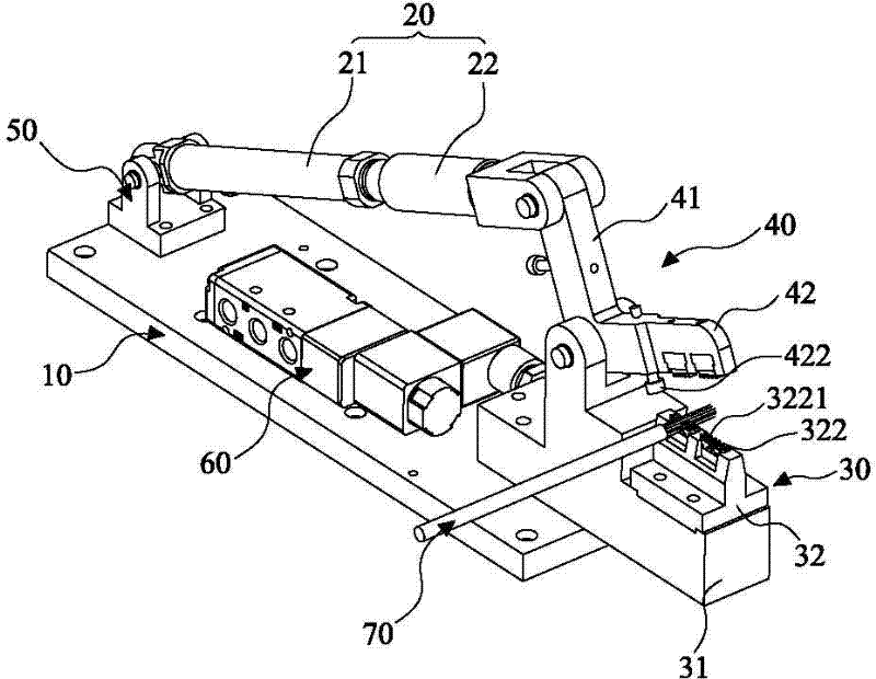
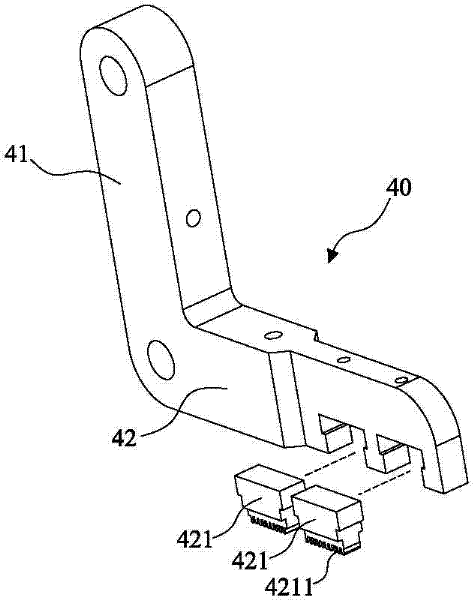
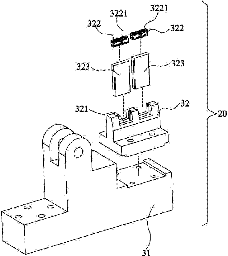
[0026] The present invention as Figure 1 to Figure 3 As shown, a base 10 , a cylinder 20 , a base 30 and a corner crimping rod 40 are included.

[0027] The base 10 is a flat plate, which is used to install the above-mentioned cylinder 20 and the base 30 , a connection seat 50 is arranged at one end of the base 10 , and a solenoid valve 60 for controlling the operation of the above-mentioned cylinder 20 is installed on the base 10 .

[0028] The cylinder 20 includes a cylinder main body 21 and a piston rod 22 , wherein one end of the cylinder main body 21 is pivotally connected to the connecting seat 50 , and the piston rod 22 is disposed at the other end of the cylinder main body 21 .

[0029] The base 30 is fixed on the other end of the base 10, and it includes a base 31 and a support base 32 replaceably mounted on the base 31. Two grooves 321 are arranged side by side on the support base 32. A replaceable wire rack 322 is accommodated in each groove 321, and a plurality o...


PUM


Abstract

The invention discloses a connector cable pressing jig, which comprises a base, a cylinder, a pedestal and a corner pressing rod. A connecting seat is arranged at one end of the base, and the cylinder comprises a cylinder body and a piston rod, wherein the cylinder body is pivoted on the connecting seat. The pedestal is fixedly mounted on the base and comprises a pedestal body and a supporting seat, the supporting seat is provided with two grooves side by side, a cable carrier is placed in each groove, and the upper face and the lower face of each cable carrier are respectively provided with a plurality of cable slots. The corner pressing rod comprises a connecting arm and a pressing arm, one end of the connecting arm is pivoted to the end of the piston rod, the corner position of the corner pressing rod is pivoted to the pedestal, two detachable pressing blocks corresponding to the two cable carriers respectively are arranged on the pressing arm, each pressing block is provided with a plurality of pressing blocks, and cables are pressed to the bottom of the cable slots by the pressing blocks when being pressed. Therefore, by means of the structure, the connector cable pressing efficiency is improved, cable connecting stability is enhanced, and the connector cable pressing jig is simple in structure and convenient in assembly.

Description

technical field [0001] The invention relates to the technology in the field of electrical connectors, in particular to a connector cable crimping jig. Background technique [0002] With the continuous rapid development of the technological era, various practical and advanced electronic and electrical products have come out one after another, which have also brought people a lot of convenience in life and work, and have the advantages of saving time, labor and high work efficiency. As a connector with fast transmission performance, it has gradually become an essential component for data, audio and video transmission in various electronic products. The rapid development of electronic products has made connectors more and more important. The product quality and production of connectors Efficiency is closely related to the development of electronic products. [0003] However, during the production process of the connector, the connector cable needs to be pressed into the wire ...

Claims


Application Information

Patent Timeline
Patent Type & Authority Applications(China)
IPC IPC(8): H01R43/00H01R43/28
Inventor 骆阳旭
Owner DONGGUAN KECHENDA ELECTRONICS TECH
Learn More