Standard gas distribution meter

A standard gas and gas distribution instrument technology, applied in the direction of gas and gas/steam mixing, mixer accessories, chemical instruments and methods, etc., can solve problems such as external environmental interference, and achieve the effect of avoiding interference

Active Publication Date: 2012-06-27
BEIJING SDL TECH
2 Cites 11 Cited by

AI-Extracted Technical Summary

Problems solved by technology

[0004] In view of this, the object of the present invention is to provide a standard gas distribution instrument to solve the problem...

Method used

Described flow controller 1 is arranged in described thermal insulation layer 2, and described thermal insulation layer 2 is used to keep the temperature of described flow controller 1, and in addition in actual gas distribution process, background gas port and range gas port and all The pipeline connected to the flow controller 1 is generally also arranged inside the insulation layer 2 to achieve the purpose of sufficient heat preservation. Moreover, the length of the pipeline connected to the background gas port and the flow controller 1, the length of the pipeline connected to the flow controller 1 and the range gas port The length of the path should ensure that the background gas and span gas enter the flow controller 1, and after mixing in the flow controller 1 and completing the heat exchange, the background gas and span gas can reach a constant temperature, and the insul...

Abstract

The embodiment of the invention discloses a standard gas distribution meter, which comprises a background gas opening, a measuring range gas opening and two flow rate controllers, wherein the two flow rate controllers respectively correspond to the background gas opening and the measuring range gas opening, and in addition, the standard gas distribution meter also comprises a heat insulation layer, a setting unit, a micro control unit (MCU) and a temperature control unit. During standard gas distribution, the flow rate controllers, pipelines connected between the background gas opening and the flow rate controllers and pipelines connected between the measuring range gas opening and the flow rate controllers are arranged in the heat insulation layer, and the temperature in the heat insulation layer is always kept at the constant temperature through the temperature control unit, so the flow rate controllers and the gas flowing into the flow rate controllers are stably kept at a certain temperature, and the external environment interference is avoided.

Application Domain

Technology Topic

Image

  • Standard gas distribution meter
  • Standard gas distribution meter
  • Standard gas distribution meter

Examples

  • Experimental program(1)

Example Embodiment

[0019] The following will clearly and completely describe the technical solutions in the embodiments of the present invention with reference to the accompanying drawings in the embodiments of the present invention. Obviously, the described embodiments are only some, not all, embodiments of the present invention. Based on the embodiments of the present invention, all other embodiments obtained by persons of ordinary skill in the art without creative efforts fall within the protection scope of the present invention.
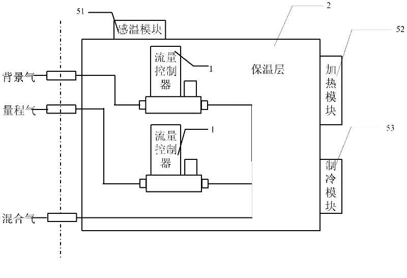
[0020] The embodiment of the present invention is used to provide a standard gas distributing instrument to solve the problem of poor accuracy of the standard gas in the prior art due to the influence of the external environment when preparing the standard gas. Its structural diagram is as follows figure 1 As shown, the standard gas distribution instrument includes a flow controller 1, a background gas port and a range gas port, and the standard gas distribution device also includes: an insulation layer 2, a setting unit 3, an MCU microprocessor unit 4 and a control unit. Temperature unit 5, where:
[0021] The flow controller 1 is arranged in the insulation layer 2, and the insulation layer 2 is used to maintain the temperature of the flow controller 1. In addition, in the actual gas distribution process, the background gas port and the range gas port are connected with the flow control The pipeline connected to the device 1 is generally also arranged inside the insulation layer 2 to achieve sufficient heat preservation. Moreover, the length of the pipeline connected to the background gas port and the flow controller 1, and the length of the pipeline connected to the range gas port and the flow controller 1 must be Ensure that the background gas and span gas enter the flow controller 1, and after mixing in the flow controller 1 and completing the heat exchange, the background gas and span gas can reach a constant temperature. The insulation layer 2 is generally made of glass Cotton, the flow controller 1 is generally a mass flow controller.
[0022] The setting unit 3 is used to set the preparation parameters and temperature parameters, and deliver the set preparation parameters and temperature parameters to the MCU microprocessor unit 4, wherein the temperature parameters include: preset temperature values ​​or temperature ranges . In actual application, the setting unit 3 is a keyboard and/or a touch screen. When the setting unit 3 is a touch screen, the touch screen can display the set preparation parameters. When the setting unit 3 is a keyboard, The setting unit also includes a display screen for displaying the preparation parameters, so as to facilitate the control of the gas distribution process.
[0023] The MCU microprocessor unit 4 is connected with the setting unit 3 and the temperature control unit 5, the MCU microprocessor unit 4 is used to receive the preparation parameters and temperature parameters delivered by the setting unit 3, and simultaneously receive the The temperature fed back by the temperature control unit 5 is compared with the temperature parameter, and a temperature adjustment instruction is sent to the temperature control unit 5 according to the comparison result, wherein the temperature adjustment instruction includes a heating instruction and a cooling instruction, when the feedback When the temperature is lower than the preset temperature value or the minimum value of the preset temperature range, a heating command is issued, and when the feedback temperature is higher than the preset temperature value or the maximum value of the preset temperature range , a cooling command is issued.
[0024] The temperature control unit 5 is installed on the thermal insulation layer 2, and the temperature control unit 5 is used to sense the temperature in the thermal insulation layer 2, and sends the sensed temperature value to the MCU microprocessor unit 4, and according to The received temperature adjustment instruction sent by the MCU microprocessor unit 4 controls the thermal insulation layer 2 to keep within the temperature value or temperature range corresponding to the temperature parameter.
[0025] Generally, the temperature control unit 5 includes a temperature sensing module 51, a heating module 52 and a refrigeration module 53, wherein the temperature sensing module 51 is connected to the MCU microprocessor unit 4, and the temperature sensing module 51 It is used to sense the temperature in the insulation layer 2, and send the sensed temperature value to the MCU microprocessor unit 4. Taking the set temperature parameter as a specific preset temperature value as an example, when the temperature sensing module When the sensed temperature value is less than the preset temperature value, the MCU microprocessor unit 4 will generate a heating instruction and send it to the heating module 52, and when the temperature value sensed by the temperature sensing module is greater than the set value , the MCU microprocessor unit 4 will generate a cooling command and send it to the cooling module 53; the heating module 52 is connected to the MCU microprocessor unit 4, and the heating module 42 is used to receive the heating command After that, heat the inside of the thermal insulation layer 2 to the temperature value delivered by the setting unit 3; the refrigeration module 53 is connected with the MCU microprocessor unit 4, and the refrigeration module 53 is used for receiving After the cooling command, cool the inside of the insulation layer 2 to the temperature value sent by the setting unit 3 . Moreover, the heating module 52 includes a heating sheet and/or a heating rod, and the cooling module 53 includes a semiconductor cold sheet and/or a water circulation cooling device.
[0026] The schematic diagram of the working process of the calibration gas preparation instrument disclosed in this embodiment is as follows: figure 2 shown, including:
[0027]First, set the configuration parameters in the setting unit 3, the configuration parameters include: span gas concentration, outlet total flow and outlet gas concentration, after the configuration parameters are delivered to the MCU microprocessor unit 4, the configuration parameters are determined by the The MCU microprocessor unit 4 calculates the flow value of the background gas and the flow value of the span gas, and then sends the obtained flow value to the respective flow controller 1, and the flow controller 1 sends the background gas according to the calculated value and span gas. At the same time, the temperature parameter is set in the setting unit 3 as required, and the temperature parameter is sent to the MCU microprocessor unit 4, and the temperature parameter includes: a preset temperature value or temperature range. In general, the temperature value is set to about 25°C at room temperature, or the temperature range is set to (24°, 27°), and other settings can be made according to different configuration requirements. At the same time, the MCU microprocessor unit 4 receives the temperature value in the thermal insulation layer 2 sensed by the temperature control unit 5 . When the sensed temperature value is less than the set temperature value, the MCU microprocessor unit 4 generates a heating command and sends it to the heating module 52, and the heating module 52 that receives the heating command will heat the insulation layer. 2 internally heated to the temperature value delivered by the setting unit 3; when the sensed temperature value is greater than the set temperature value, the MCU microprocessor unit 4 generates a cooling command and sends it to the cooling module 53, receiving The refrigerating module 53 that receives the refrigerating command will refrigerate the interior of the thermal insulation layer 2 to the temperature delivered by the setting unit 3 , so that the temperature of the gas in the flow controller 1 remains stable.
[0028] In the standard gas distribution instrument disclosed in the embodiment of the present invention, the pipeline connected between the flow controller 1, the background gas port and the flow controller 1 and the pipeline connected between the range gas port and the flow controller 1 are placed on the insulation layer 2 In the process of preparing standard gas, the temperature of the flow controller 1 is maintained by the insulation layer 2, and the temperature control unit 5 installed on the insulation layer 2 is added to keep the insulation layer 2 at Within the preset temperature range, the gas entering the flow controller 1 and the flow controller 1 are kept relatively stable at a certain temperature, avoiding the interference of the external environment.
[0029] The above description of the disclosed embodiments is provided to enable any person skilled in the art to make or use the invention. Various modifications to these embodiments will be readily apparent to those skilled in the art, and the general principles defined herein may be implemented in other embodiments without departing from the spirit or scope of the invention. Therefore, the present invention will not be limited to the embodiments shown herein, but is to be accorded the widest scope consistent with the principles and novel features disclosed herein.

PUM

no PUM

Description & Claims & Application Information

We can also present the details of the Description, Claims and Application information to help users get a comprehensive understanding of the technical details of the patent, such as background art, summary of invention, brief description of drawings, description of embodiments, and other original content. On the other hand, users can also determine the specific scope of protection of the technology through the list of claims; as well as understand the changes in the life cycle of the technology with the presentation of the patent timeline. Login to view more.

Similar technology patents

Classification and recommendation of technical efficacy words

Why Eureka
Try Eureka