Fume exhaust layout structure for subway platform and screen door system

A technology for subway platform and layout structure, which is applied in the directions of stations, smoke removal, railway car body parts, etc.

Active Publication Date: 2012-06-27
SHANGHAI TUNNEL ENGINEERING RAILWAY TRANSPORTATION DESIGN INSTITUTE
View PDF5 Cites 3 Cited by
  • Summary
  • Abstract
  • Description
  • Claims
  • Application Information

AI Technical Summary

Problems solved by technology

[0004] One way to deal with it is to select the corresponding smoke exhaust fan to exhaust the smoke through the platform smoke exhaust pipe. In this way, the cross-sectional area of ​​the smoke exhaust pipe is large, and the height of the entire platform of the station needs to be increased, which increases the construction cost of the station.
The second method is to open the station screen door or the openable and closable air outlet of the screen door, and use the emergency fan or heat exhaust fan installed in the section to open it, and indirectly lead the smoke from the platform waiting area to the station section to be discharged, so that artificial The range of smoke diffusion is increased, and the opening of the screen door increases the risk of secondary disasters
The third method is to set the stairway in a manner similar to that of a closed stairwell to reduce the amount of smoke exhaust. This method makes the architectural space of the platform unfavorable

Method used


Image

  • Fume exhaust layout structure for subway platform and screen door system
  • Fume exhaust layout structure for subway platform and screen door system
  • Fume exhaust layout structure for subway platform and screen door system

Examples


Embodiment 1

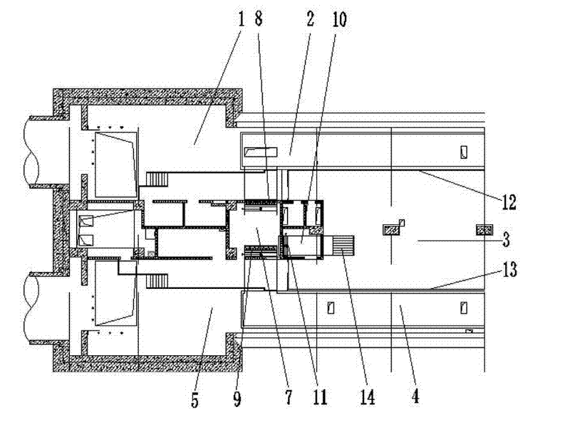
[0018] Embodiment one: if figure 1 As shown, track 1 and track 5 are the tracks of the up and down subway, which are located on both sides of the platform waiting area 3 . Screen doors 12, 13 are located on both sides of the platform waiting area 3. The platform waiting area 3 is provided with a heat exhaust air pipe 2 and a heat exhaust air pipe 4 respectively above the track, and the two heat exhaust air pipes are respectively connected to the heat exhaust chamber 7 and the heat exhaust fan system located on one side of the platform waiting area. Air valves 8 and 9 are respectively provided at the joints of the exhaust heat pipes 2 and 4 with the heat discharge chamber 7 to control the working state of the exhaust heat pipes 2 and 4 . The heat exhausting chamber 7 has a centralized smoke exhaust port 6 on the side surface adjacent to the waiting platform area, that is, the opening of the concentrated smoke exhaust port 6 leads to the platform waiting area 3, and the form of...

Embodiment 2

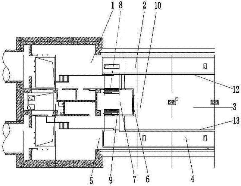
[0019] Embodiment two: if figure 2 As shown, the concentrated smoke exhaust port 6 is connected with a smoke exhaust pipe 10, and the joint between the smoke exhaust pipe 10 and the heat exhaust chamber 7 is provided with a damper 11, and the damper 11 controls the work of the smoke exhaust pipe 10 and the centralized exhaust vent 14. state. The air valves 8 and 9 at the joints between the exhaust heat ducts 2 and 4 and the heat exhaust chamber 7 should be located at the height of the exhaust chamber 7, so that the heat exhaust effect in the rail area is better. The setting form of the heat exhaust air duct 10 can be changed according to the form of the concentrated smoke exhaust port 6. If the concentrated smoke exhaust port 6 is composed of a plurality of small smoke exhaust ports, the heat exhaust air duct 10 can also be made up of a plurality of small exhaust vents. The heat exhaust air pipe group composed of hot air pipes.

[0020] In the above-mentioned embodiment, a ...


PUM


Abstract

The invention relates to the field of ventilation and fire prevention in track transport, in particular to a fume exhaust layout structure for subway platform and screen door system. The structure is characterized in that a fume exhaust is arranged at a side of a heat exhaust chamber close to the waiting platform, and the fume exhaust is connected with a control valve. The structure of the invention has the following advantages: the arranged fume exhaust or fume exhaust pipe helps to exhaust the fume of the platform zone inside the screen door, to form the fume exhaust way which combines even fume exhaust of initial vent pipes of the station and concentrated fume exhaust of heat exhaust fans. In this way, the normal fume exhaust requirement of the platform is satisfied, and the requirement of wind speed of 1.5m/s of stairway is also satisfied; the scale of the station is not significantly affected, and the fume is limited in the waiting zone of the station, so that the diffusion range of fume is not increased, and the secondary damage possibly caused by opening the screen door is avoided.

Description

[0001] technical field [0002] The invention relates to rail transit ventilation and fire protection, in particular to a subway platform smoke exhaust layout structure which is also used as a screen door system. Background technique [0003] When a fire breaks out on the platform of an underground rail transit station, in addition to maintaining the normal 60m 3 / min.m 2 In addition, it is also necessary to maintain a downward wind speed of 1.5m / s at the stair mouth of the platform and the station hall, so that the smoke exhaust volume of the platform is changed from the conventional 8×10⁴m 3 / h ~10 4 m 3 / h increased to 20×10 4 m 3 / h~30×10 4 m 3 / h. [0004] One treatment method is to select the corresponding smoke exhaust fan to exhaust the smoke through the platform smoke exhaust pipe. In this way, the cross-sectional area of ​​the smoke exhaust pipe is large, and the height of the entire platform of the station needs to be increased, which increases the constru...

Claims


Application Information

Patent Timeline
Patent Type & Authority Applications(China)
IPC IPC(8): B08B15/00B61B1/00
Inventor 郑晋丽阎正才瞿立张文斌
Owner SHANGHAI TUNNEL ENGINEERING RAILWAY TRANSPORTATION DESIGN INSTITUTE
Why Eureka
Try Eureka