
Device for automatically balancing moving die table

An automatic balancing and moving table technology, applied in the field of balancing devices, can solve the problems of unstable mold clamping, large reactive power loss, easy to cause vibration, etc., to achieve stable mold clamping, improve efficiency, and reduce vibration effects.

Active Publication Date: 2012-06-27
GUANGDONG DESIGNER MASCH CO LTD
View PDF4 Cites 3 Cited by
  • Summary
  • Abstract
  • Description
  • Claims
  • Application Information

AI Technical Summary

Problems solved by technology

However, the above-mentioned structure with added springs still has the following disadvantages: during the reciprocating motion of the upper and lower template movable tables, the connecting rod drive mechanism needs to exert a greater effect on the upper and lower template movable tables. In order to overcome the weight of the movable table of the upper template and the movable table of the lower template, the reactive power loss is relatively large; in addition, the rebound of the spring after being compressed produces a large instantaneous impulse force on the movable table of the upper template and the movable table of the lower template, And it is difficult to control, so it is easy to cause vibration, resulting in unstable mold clamping

Method used


Image

  • Device for automatically balancing moving die table
  • Device for automatically balancing moving die table

Examples


Embodiment Construction

[0011] Further description will be given below in conjunction with the accompanying drawings and preferred embodiments of the present invention.

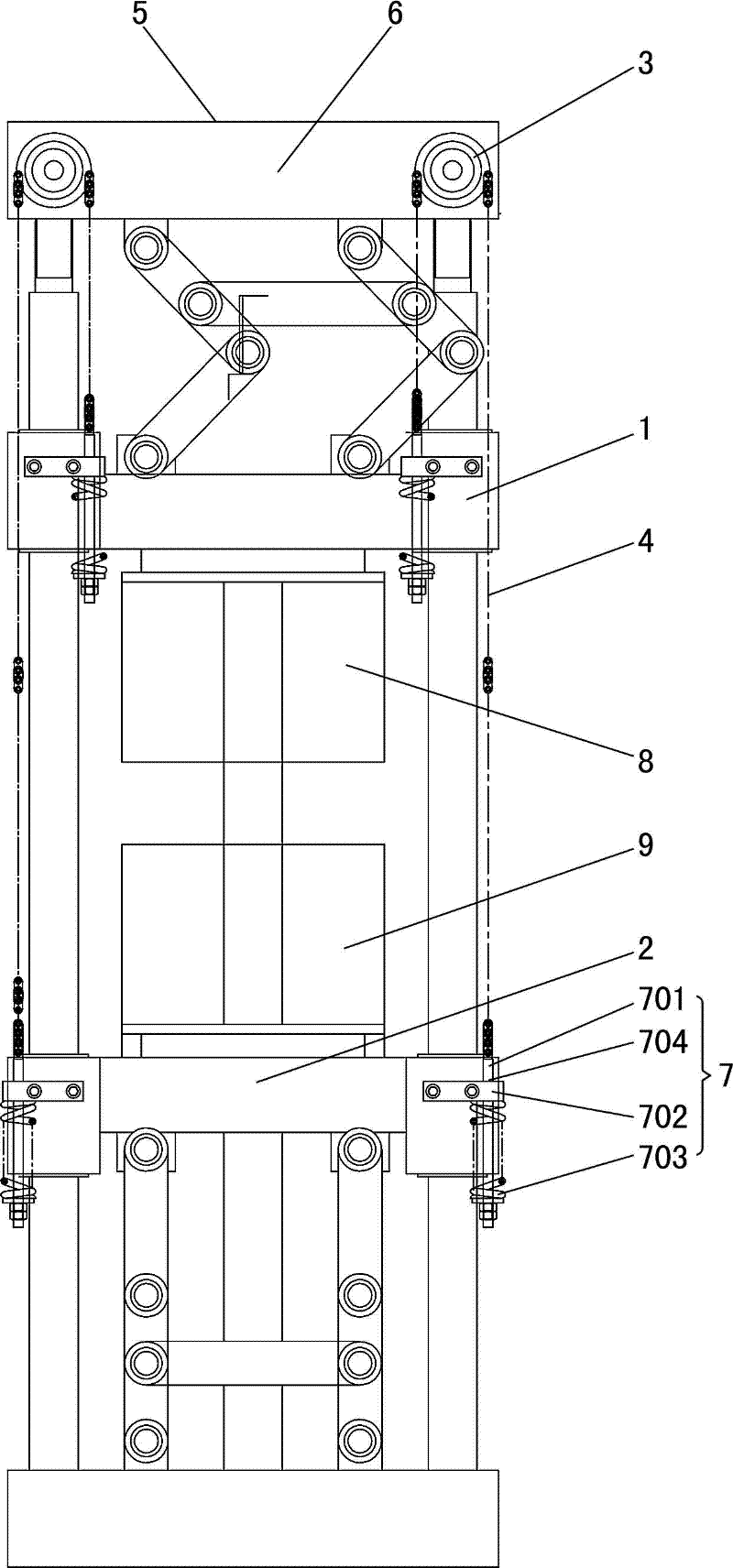
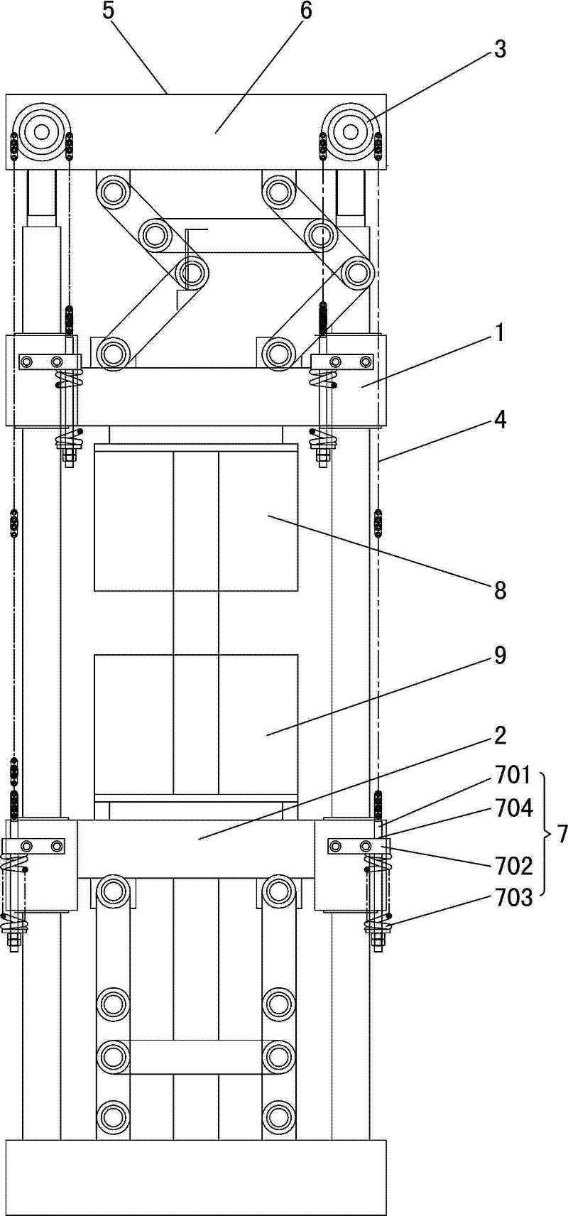
[0012] As shown in the accompanying drawings, this automatic balancing device for the movable mold table includes the upper template movable table 1, the lower template movable table 2, two sprockets 3 and two chains 4 of the thermoforming machine; the two sprockets 3 can respectively Rotate and install on the frame 5 of the thermoforming machine, and respectively above the lower edges on both sides of the upper fixed table 6 of the thermoforming machine; the chain 4 bypasses the sprocket 3, and one end of the chain 4 is connected with the upper template movable table 1, The other end of chain 4 is connected with lower formwork moving table 2.

[0013] This automatic balancing device for the movable die table also includes a buffer mechanism 7, the upper template movable table 1 and the lower template movable table 2 are connected t...


PUM


Abstract

The invention relates to a device for automatically balancing a moving die table. The device comprises an upper die plate moving table and a lower die plate moving table of a hot former, and is characterized by also comprising at least one supporting piece and at least one soft connection strip, wherein the supporting piece is arranged on a stander of the hot former in a rotatable manner and positioned above the lower edge of an upper fixed table of the hot former; the soft connection strip bypasses the supporting piece; and one end of the soft connection strip is connected with the upper die plate moving table, and the other end of the soft connection strip is connected with the lower die plate moving table. The upper die plate moving table and the lower die plate moving table are mutually pulled through the soft connection strip by taking the supporting piece as a pivot, so that the weights of the upper die plate moving table and the lower die plate moving table are counteracted; therefore, the inertial impact of an upper die plate and a lower die plate during die assembly is reduced, the vibration is reduced, and the die assembly is relatively stable; furthermore, due to the mutual traction action of the upper die plate moving table and the lower die plate moving table, one die plate moving table rises, and the other die plate moving table falls, so that the rising acting forces of the upper die plate moving table and the lower die plate moving table are relatively small, the reactive power loss is reduced, and the efficiency is improved.

Description

technical field [0001] The invention relates to a balancing device, in particular to an automatic balancing device for a movable mold table. Background technique [0002] At present, a thermoforming machine generally includes a frame, a guide column, an upper fixed table, an upper template movable table, an upper template, a lower fixed table, a lower template movable table, and a lower template. Both the upper template movable table and the lower template movable table are installed on the guide The upper formwork is connected to the upper formwork movable table, the lower formwork is connected to the lower formwork movable table, the upper formwork movable table and the upper fixed table, and the lower formwork movable table and the lower fixed table are also connected. Equipped with connecting rod drive mechanism. When this kind of thermoforming machine is mold clamping or blanking, the upper and lower template movable tables reciprocate up and down. Due to the weight of...

Claims


Application Information

Patent Timeline
Patent Type & Authority Applications(China)
IPC IPC(8): B29C51/26
CPCY02P70/10
Inventor 罗庆青周昭文章俊波
Owner GUANGDONG DESIGNER MASCH CO LTD
Learn More