Braking starter of horizontal axle windmill
A starting device and wind turbine technology, applied in electromechanical devices, asynchronous induction motors, asynchronous induction clutches/brakes, etc., can solve the problems of low wind energy utilization efficiency, difficulty in starting, and high cut-in wind speed, so as to improve effective wind energy utilization efficiency, The effect of reducing mechanical wear and reducing inertial impact
- Summary
- Abstract
- Description
- Claims
- Application Information
AI Technical Summary
Problems solved by technology
Method used
Image
Examples
Embodiment 1
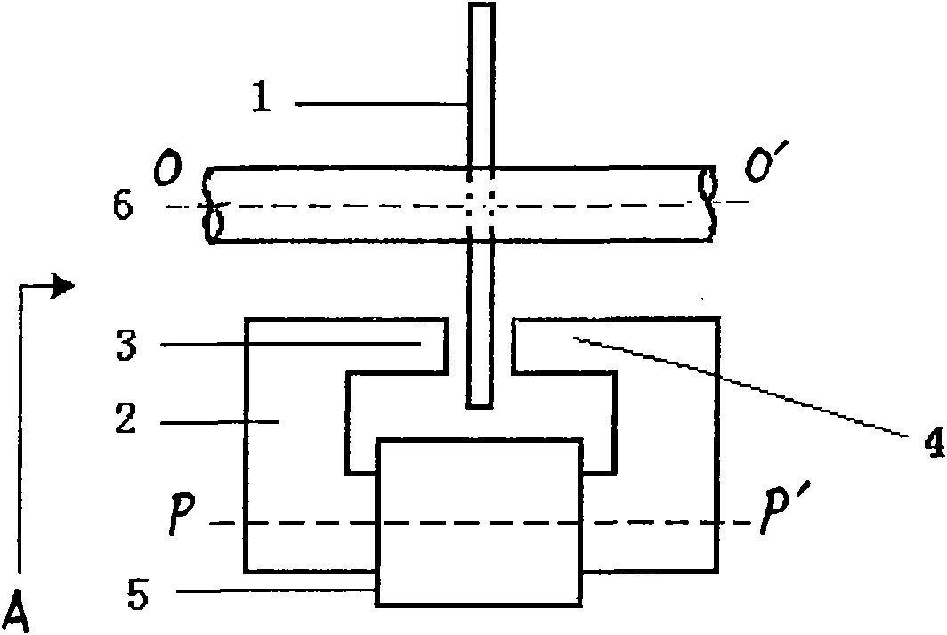
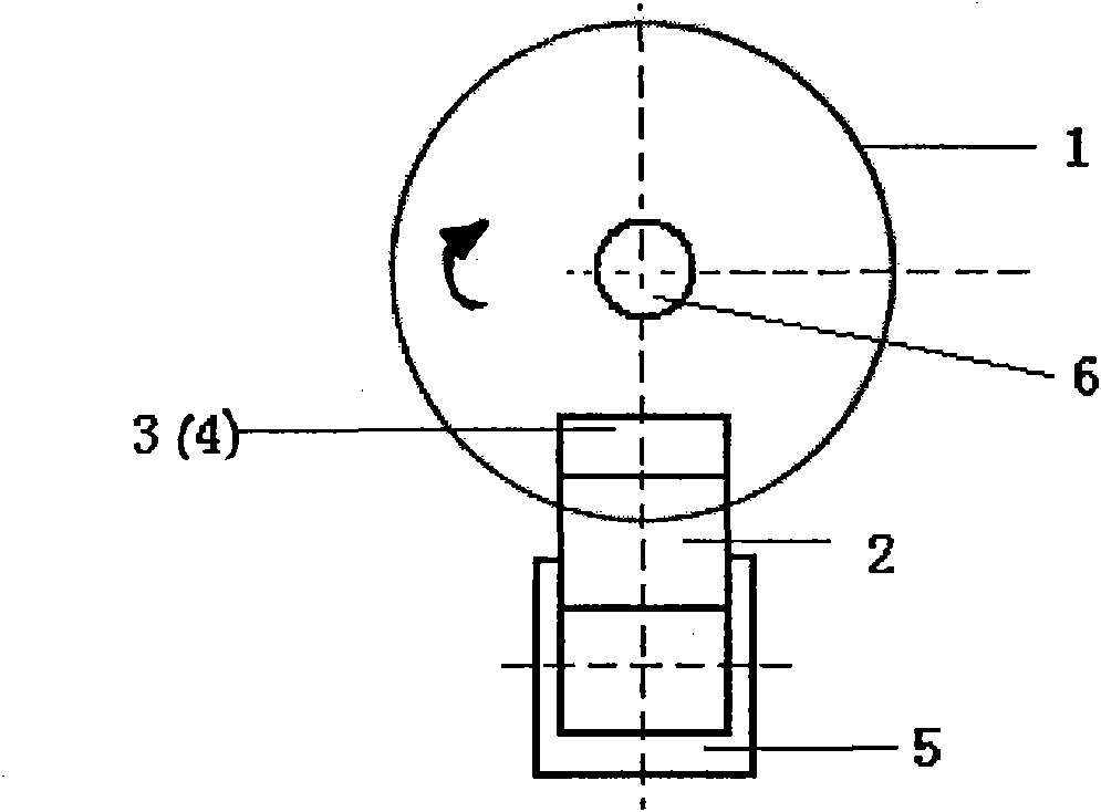
[0009] Such as figure 1 , figure 2 As shown, the brake disc 1 is installed on the transmission shaft 6, the plane where the brake disc 1 is located is perpendicular to the axis OO' of the transmission shaft 6, the axis PP' of the electromagnetic coil 5 is parallel to the axis OO' of the transmission shaft 6, and the U-shaped electromagnet 2 The middle end of the lower part is installed in the electromagnetic coil 5, the two magnetic poles 3, 4 of the U-shaped electromagnet 2 are installed oppositely, and the outer edge of the brake disc 1 is located between the two opposite magnetic poles 3, 4 of the U-shaped electromagnet 2, Several U-shaped electromagnets 2 are respectively installed along the circumferential direction of the brake disc 1 . When the transmission shaft 6 is a high-speed rotating shaft, when braking, the electromagnet coils 5 are energized at the same time, so that the magnetic field directions of the electromagnets 2 are the same, and the rotating brake dis...
Embodiment 2
[0011] Such as figure 1 , figure 2 As shown, the brake disc 1 is installed on the transmission shaft 6, the plane where the brake disc 1 is located is perpendicular to the axis OO' of the transmission shaft 6, the axis PP' of the electromagnetic coil 5 is parallel to the axis OO' of the transmission shaft 6, and the U-shaped electromagnet 2 The middle end of the lower part is installed in the electromagnetic coil 5, the two magnetic poles 3, 4 of the U-shaped electromagnet 2 are installed oppositely, and the outer edge of the brake disc 1 is located between the two opposite magnetic poles 3, 4 of the U-shaped electromagnet 2, Several U-shaped electromagnets 2 are respectively installed along the circumferential direction of the brake disc 1 . When the wind turbine starts at a low wind speed, the two magnetic poles 3 and 4 of each electromagnet 2 rotate through an angle, and are evenly distributed on both sides of the brake disc 1, and each electromagnetic coil 5 is energized...
PUM
 Abstract
Description
Claims
Application Information
 - R&D
- Intellectual Property
- Life Sciences
- Materials
- Tech Scout
- Unparalleled Data Quality
- Higher Quality Content
- 60% Fewer Hallucinations
Browse by: Latest US Patents, China's latest patents, Technical Efficacy Thesaurus, Application Domain, Technology Topic, Popular Technical Reports.
© 2025 PatSnap. All rights reserved.Legal|Privacy policy|Modern Slavery Act Transparency Statement|Sitemap|About US| Contact US: help@patsnap.com


