Positioning system for laser printer

A laser printer and positioning system technology, applied in printing devices, printing and other directions, can solve problems such as poor compatibility, frequent alarms, offset printing, etc., and achieve the effects of long service life, convenient operation and cost reduction

Active Publication Date: 2012-06-27
NANTONG FUJITSU MICROELECTRONICS
View PDF6 Cites 3 Cited by
  • Summary
  • Abstract
  • Description
  • Claims
  • Application Information

AI Technical Summary

Problems solved by technology

[0003] 1. It is necessary for the positioning pin to match the positioning hole on the product, and the difference should not be too large. If the diameter of the positioning hole of the product is larger than the diameter of the positioning pin, it will cause the product to move and the positioning will be inaccurate; if the diameter of the positioning hole of the product If it is very close to the diameter of the positioning pin, it will easily lead to product deformation and partial printing, or frequent alarms will affect production efficiency
[0004] 2. Poor versatility, different products need to use different positioning pins
[0005] 3. Poor compatibility and relatively soft products have particularly high requirements for positioning pins, otherwise they are easily deformed
[0006] 4. When working on relatively hard products, the positioning pin is easy to break
[0007] 5. When working on relatively thick products, it is easy to scratch the coating inside the positioning hole, forming burrs on the coating, which affects the use
[0008] 6. Due to the different sizes of the positioning pins, the bases for mounting the positioning pins will be different, and the cost will increase

Method used


Image

  • Positioning system for laser printer
  • Positioning system for laser printer
  • Positioning system for laser printer

Examples


Embodiment Construction

[0033] Embodiments of the present invention will be described below with reference to the drawings. Elements and features described in one drawing or one embodiment of the present invention may be combined with elements and features shown in one or more other drawings or embodiments. It should be noted that representation and description of components and processes that are not related to the present invention and known to those of ordinary skill in the art are omitted from the drawings and descriptions for the purpose of clarity.

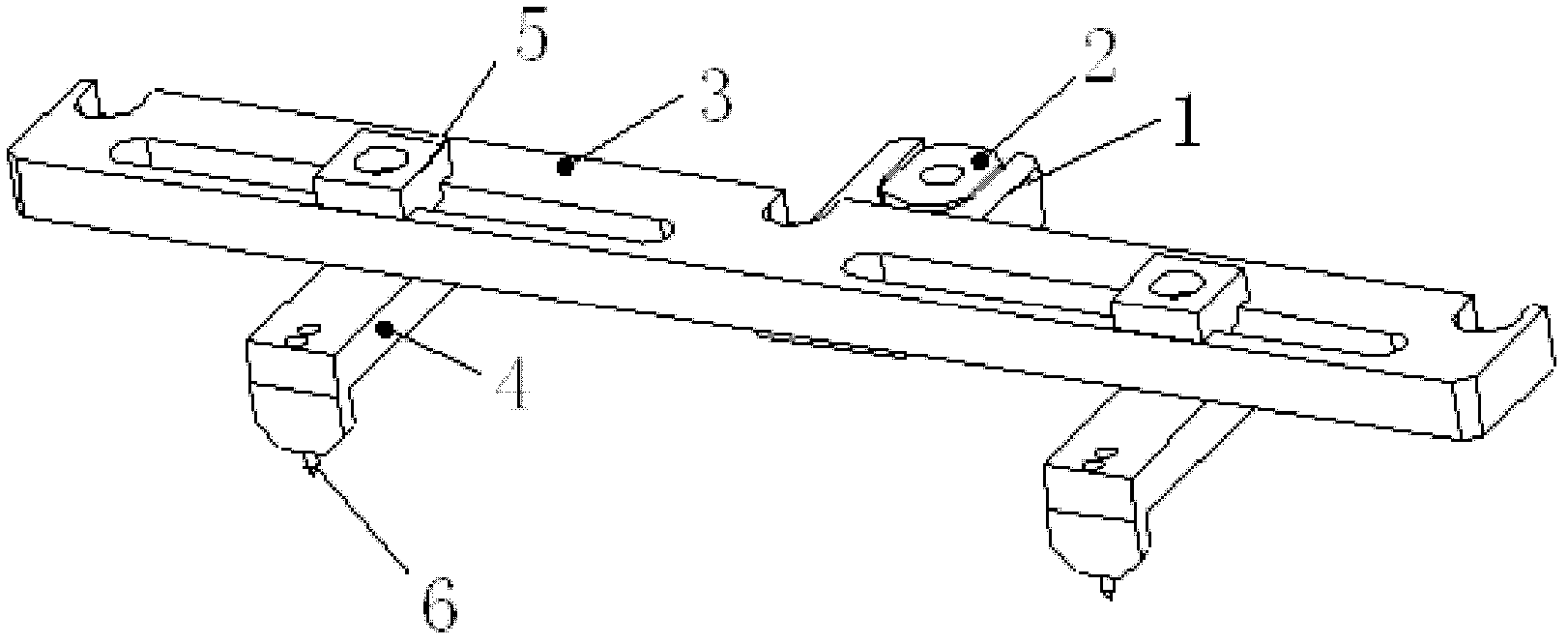
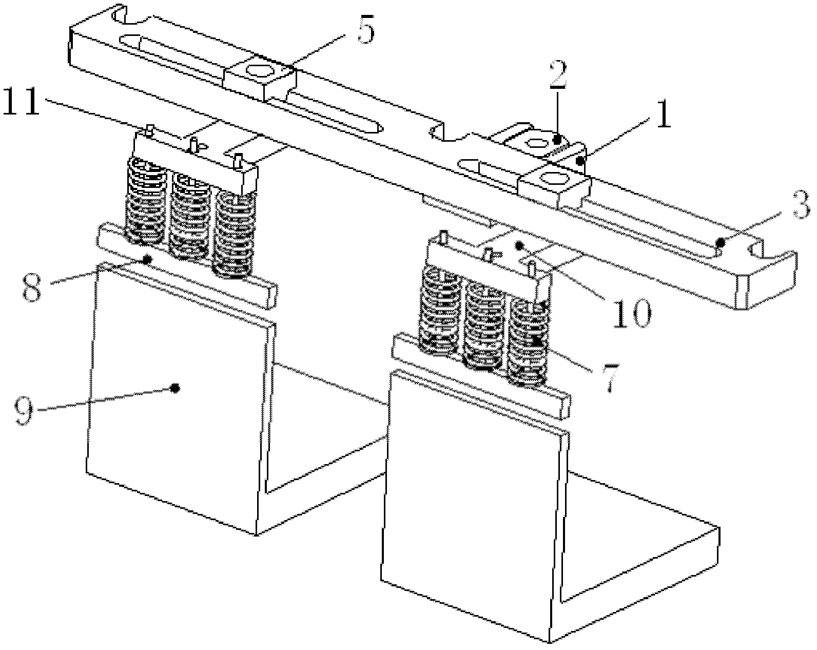
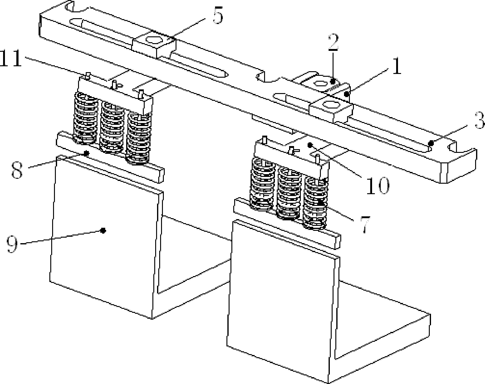
[0034] see figure 2 , a laser printer positioning system, comprising a positioning plate 3 and a cylinder clip 1 arranged on the positioning plate 3, the cylinder clip 1 is connected to the printer through a cylinder clip joint 2, the printer positioning system also includes a positioning The positioning device below the plate 3, the positioning device includes an upper pressing block assembly and a lower pressing block 9, the upper pressing bloc...


PUM


Abstract

The invention relates to a printer, in particular to a positioning system for a laser printer, which comprises a positioning plate, a cylinder clamp and a positioning device, wherein the cylinder clamp is arranged on the positioning plate and connected with the printer through a cylinder clamp connector, and the positioning device is arranged below the positioning plate. The positioning device comprises an upper pressing block component and a lower pressing block, the upper pressing block component is slidably connected with the positioning plate, and the lower pressing block matched with the upper pressing block component is fixed below the upper pressing block component. The positioning system for the laser printer has the advantages of accuracy in positioning, difficulty in damaging positioned products, high universality, high compatibility and low cost.

Description

technical field [0001] The present application relates to a laser printer, in particular to a positioning system for a laser printer. Background technique [0002] At present, the printing devices in the prior art all use a positioning system with positioning pins for product positioning. Such as figure 1 As shown, the printer positioning system in the prior art includes a positioning plate 3 and a cylinder clamp 1 arranged on the positioning plate 3, the cylinder clamp 1 is connected to the printer through the cylinder clamp connector 2, and the positioning device includes a sliding The connecting block and the positioning pin 6, the sliding connecting block includes the base locking block 5 and the positioning pin base 4, the positioning device is connected with the positioning plate 3 through the base locking block 5, and the positioning pin 6 is fixedly connected to the positioning pin base 4 the lower surface. This positioning system has the advantages of accurate po...

Claims


Application Information

Patent Timeline
Patent Type & Authority Applications(China)
IPC IPC(8): B41J29/00B41J2/435
Inventor 沈正安朱海斌赵新民马建
Owner NANTONG FUJITSU MICROELECTRONICS
Why Eureka
Try Eureka